DTC C1787 EMS Switch Circuit (Test Mode DTC) |
| DTC No. | DTC Detection Condition | Trouble Area |
| C1787 | There is no change in the absorber control switch signal when performing the Test Mode check. |
|
| 1.READ VALUE OF INTELLIGENT TESTER |
Connect the intelligent tester to DLC3.
Turn the engine switch on (IG) and turn the intelligent tester main switch on.
Select "Data List" mode on the intelligent tester (Click here).
| Item | Measurement Item/ Range (Display) | Normal Condition | Diagnostic Note |
| Damping Force Switch 1 | Damper force switch 1 (absorber control switch) / ON or OFF | The same as absorber control switch position | Operate the absorber control switch |
Operate the absorber control switch and check its operation in the Data List on the intelligent tester display.
|
| ||||
| OK | |
| 2.RECONFIRM DTC |
Clear the DTC (Click here).
Perform the Test Mode (Click here).
Check if the same DTC is recorded (Click here).
| Result | Proceed To |
| DTC is output | A |
| DTC is output (When troubleshooting accordance with the PROBLEM SYMPTOMS TABLE) | B |
| DTC is not output | C |
|
| ||||
|
| ||||
| A | ||
| ||
| 3.INSPECT ABSORBER CONTROL SWITCH |
 |
Remove the absorber control switch.
Disconnect the absorber control switch connector.
Measure the resistance according to the value(s) in the table below.
| Tester Connection | Switch Position | Specified Condition |
| Switch terminal 4 - Switch terminal 3 | NORM | 10 kΩ or higher (No Continuity) |
| Switch terminal 4 - Switch terminal 3 | SPORT | Below 1 Ω (Continuity) |
|
| ||||
| OK | |
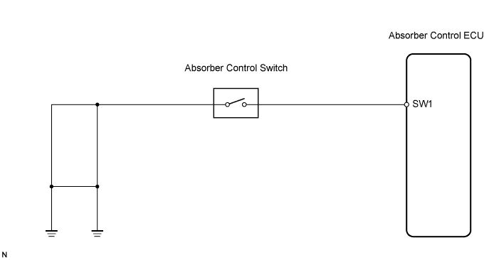
| 4.CHECK HARNESS AND CONNECTOR (ABSORBER CONTROL SWITCH TO ABSORBER CONTROL ECU, BODY GROUND) |
 |
Disconnect the absorber control ECU connector.
Measure the resistance according to the value(s) in the table below.
| Tester Connection | Specified Condition |
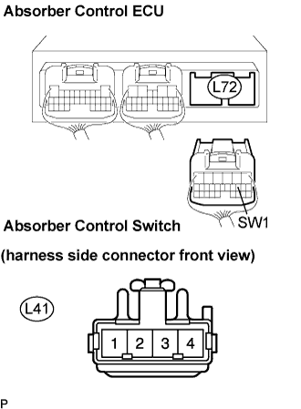
| L72-9 (SW1) - L41-4 | Below 1 Ω |
| L72-9 (SW1) - Body ground | 10 kΩ or higher |
Measure the resistance according to the value(s) in the table below.
| Tester Connection | Specified Condition |
| L41-3 - Body ground | Below 1 Ω |
|
| ||||
| OK | |
| 5.RECONFIRM DTC |
Clear the DTC (Click here).
Perform Test Mode (Click here).
Check if the same DTC is recorded (Click here).
| Result | Proceed To |
| DTC is output | A |
| DTC is output (When troubleshooting accordance with the PROBLEM SYMPTOMS TABLE) | B |
| DTC is not output | C |
|
| ||||
|
| ||||
| A | ||
| ||
