ENTRY AND START SYSTEM > TERMINALS OF ECU |
| CHECK CERTIFICATION ECU |
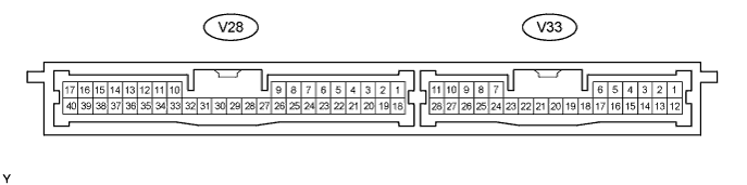
Disconnect the V28 ECU connector.
Measure the voltage and resistance of the wire harness side connector.
| Symbols (Terminal No.) | Wiring Color | Terminal Description | Condition | Specified Condition |
| +B1 (V28-1) - Body ground | R - Body ground | +B power supply | Always | 10 to 14 V |
| IG (V28-18) - Body ground | B - Body ground | Ignition power supply | Engine switch off | Below 1 V |
| IG (V28-18) - Body ground | B - Body ground | Ignition power supply | Engine switch on (IG) | 10 to 14 V |
| E (V28-17) - Body ground | W-B - Body ground | Ground | Always | Below 1 Ω |
Reconnect the V28 ECU connector.
Measure the voltage of the connectors.
| Symbols (Terminal No.) | Wiring Color | Terminal Description | Condition | Specified Condition |
| CLG1 (V28-33) - CG1B (V28-34) | W - R | Door electrical key oscillator (front LH) sensor signal | All doors closed, all doors locked and engine switch off | Alternating between 5 V and below 1 V |
| CLG1 (V28-33) - CG1B (V28-34) | W - R | Door electrical key oscillator (front LH) sensor signal | Door unlocked or door open | Below 1 V |
| SEN1 (V28-22) - E (V28-17) | V - W-B | Touch sensor detection signal | Outside door handle touched | 10 to 14 V |
| SEN1 (V28-22) - E (V28-17) | V - W-B | Touch sensor detection signal | Outside door handle not touched | Below 1 V |
| SEL1 (V28-5) - E (V28-17) | B - W-B | Touch sensor activation control signal | Key at least 3 m (9.8 ft.) away from door | 10 to 14 V |
| SEL1 (V28-5) - E (V28-17) | B - W-B | Touch sensor activation control signal | Close to door | Below 1 V |
| CLG2 (V28-35) - CG2B (V28-36) | B - W*1 W - R*2 | Door electrical key oscillator (front RH) sensor signal | All doors closed, all doors locked and engine switch off | Alternating between 5 V and below 1 V |
| CLG2 (V28-35) - CG2B (V28-36) | B - W*1 W - R*2 | Door electrical key oscillator (front RH) sensor signal | Door unlocked or door open | Below 1 V |
| SEN2 (V28-23) - E (V28-17) | R - W-B*1 V - W-B*2 | Touch sensor detection signal | Outside door handle touched | 10 to 14 V |
| SEN2 (V28-23) - E (V28-17) | R - W-B*1 V - W-B*2 | Touch sensor detection signal | Outside door handle not touched | Below 1 V |
| SEL2 (V28-6) - E (V28-17) | G - W-B*1 B - W-B*2 | Touch sensor activation control signal | Key at least 3 m (9.8 ft.) away from door | 10 to 14 V |
| SEL2 (V28-6) - E (V28-17) | G - W-B*1 B - W-B*2 | Touch sensor activation control signal | Close to door | Below 1 V |
| CLG3 (V33-8) - CG3B (V28-9) | R - W*1 B - Y*2 | Door electrical key oscillator (rear LH) sensor signal | All doors closed, all doors locked and engine switch off | Alternating between 5 V and below 1 V |
| CLG3 (V33-8) - CG3B (V28-9) | R - W*1 B - Y*2 | Door electrical key oscillator (rear LH) sensor signal | Door unlocked or door open | Below 1 V |
| SEN3 (V33-28) - E (V28-17) | BR - W-B*1 SB - W-B*2 | Touch sensor detection signal | Outside door handle touched | 10 to 14 V |
| SEN3 (V33-28) - E (V28-17) | BR - W-B*1 SB - W-B*2 | Touch sensor detection signal | Outside door handle not touched | Below 1 V |
| SEL3 (V33-1) - E (V28-17) | O - W-B*1 LG - W-B*2 | Touch sensor activation control signal | Key at least 3 m (9.8 ft.) away from door | 10 to 14 V |
| SEL3 (V33-1) - E (V28-17) | O - W-B*1 LG - W-B*2 | Touch sensor activation control signal | Close to door | Below 1 V |
| CLG4 (V33-10) - CG4B (V33-11) | B - Y*1 R - W*2 | Door electrical key oscillator (rear RH) sensor signal | All doors closed, all doors locked and engine switch off | Alternating between 5 V and below 1 V |
| CLG4 (V33-10) - CG4B (V33-11) | B - Y*1 R - W*2 | Door electrical key oscillator (rear RH) sensor signal | Door unlocked or door open | Below 1 V |
| SEN4 (V33-27) - E (V28-17) | O - W-B*1 BR - W-B*2 | Touch sensor detection signal | Outside door handle touched | 10 to 14 V |
| SEN4 (V33-27) - E (V28-17) | O - W-B*1 BR - W-B*2 | Touch sensor detection signal | Outside door handle not touched | Below 1 V |
| SEL4 (V33-2) - E (V28-17) | LG - W-B*1 O - W-B*2 | Touch sensor activation control signal | Key at least 3 m (9.8 ft.) away from door | 10 to 14 V |
| SEL4 (V33-2) - E (V28-17) | LG - W-B*1 O - W-B*2 | Touch sensor activation control signal | Close to door | Below 1 V |
| CLG5 (V28-11) - CG5B (V28-12) | GR - BR | Indoor electrical key oscillator (front) sensor signal | 30 seconds after driver side door opened and closed, engine switch off | Alternating between 5 V and below 1 V |
| CLG5 (V28-11) - CG5B (V28-12) | GR - BR | Indoor electrical key oscillator (front) sensor signal | Within 30 seconds driver side door opened and closed, engine switch off | Below 1 V |
| CLG6 (V28-13) - CG6B (V28-14) | Y - L | Indoor electrical key oscillator (rear) sensor signal | 30 seconds after driver side door opened and closed, engine switch off | Alternating between 5 V and below 1 V |
| CLG6 (V28-13) - CG6B (V28-14) | Y - L | Indoor electrical key oscillator (rear) sensor signal | Within 30 seconds driver side door opened and closed, engine switch off | Below 1 V |
| CLG7 (V28-15) - CG7B (V28-16) | P - V | Luggage electrical key oscillator (inner) sensor signal | Luggage compartment door opening switch OFF | Alternating between 5 V and below 1 V |
| CLG7 (V28-15) - CG7B (V28-16) | P - V | Luggage electrical key oscillator (inner) sensor signal | Luggage compartment door opening switch ON | Below 1 V |
| CLG8 (V28-31) - CG8B (V28-32) | L - LG | Luggage electrical key oscillator (outer) sensor signal | Luggage compartment door opening switch OFF | Alternating between 5 V and below 1 V |
| CLG8 (V28-31) - CG8B (V28-32) | L - LG | Luggage electrical key oscillator (outer) sensor signal | Luggage compartment door opening switch ON | Below 1 V |
| RCO (V28-29) - E (V28-17) | P - W-B | Entry door control receiver power source | All doors closed, all doors locked and engine switch off | 0 to 6 V |
| RCO (V28-29) - E (V28-17) | P - W-B | Entry door control receiver power source | Door unlocked or door open | Below 1 V |
| RSSI (V28-39) - E (V28-17) | O - W-B | Entry door control receiver electric wave existence signal | All doors closed, all doors locked and engine switch off | 0 to 5 V |
| RSSI (V28-39) - E (V28-17) | O - W-B | Entry door control receiver electric wave existence signal | Door unlocked or door open | Below 1 V |
| RDA (V28-38) - E (V28-17) | G - W-B | Entry door control receiver data input signal | All doors closed, all doors locked and engine switch off | Below 1 V |
| RDA (V28-38) - E (V28-17) | G - W-B | Entry door control receiver data input signal | Door unlocked or door open | Approx. 6 to 7 V |
| CHECK COWL SIDE JUNCTION BLOCK RH ASSEMBLY (MULTIPLEX NETWORK BODY ECU) |
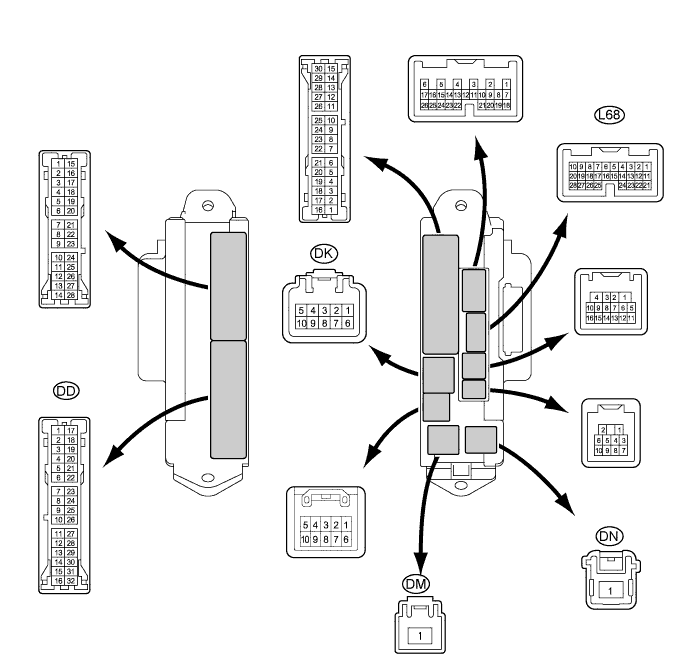
Disconnect the DD, DK, DM and DN junction block connectors.
Measure the voltage and resistance of the wire harness side connectors.
| Symbols (Terminal No.) | Wiring Color | Terminal Description | Condition | Specified Condition |
| BECU (DK-5) - Body ground | G-R - Body ground | +B (ECUB) engine supply | Always | 10 to 14 V |
| ALTB (DM-1) - Body ground | B - Body ground | +B (power system, generator system) power supply | Always | 10 to 14 V |
| BATB (DN-1) - Body ground | R - Body ground | +B (power system, generator system) power supply | Always | 10 to 14 V |
| GND2 (DD-7) - Body ground | W-B - Body ground | Ground | Always | Below 1 Ω |
Reconnect the DD, DK, DM and DN junction block connectors.
Measure the resistance of the connectors.
| Symbols (Terminal No.) | Wiring Color | Terminal Description | Condition | Specified Condition |
| TSW (L68-2) - GND2 (DD-7) | BR - W-B | Luggage compartment door opener cancel switch signal | Luggage compartment door opener cancel switch not pushed | 10 kΩ or higher |
| TSW (L68-2) - GND2 (DD-7) | BR - W-B | Luggage compartment door opener cancel switch signal | Luggage compartment door opener cancel switch pushed | Below 1 Ω |
| CHECK MULTIPLEX NETWORK DOOR ECU FRONT LH |

Disconnect the O3 and O4 ECU connectors.
Measure the resistance and voltage of the wire harness side connectors.
| Symbols (Terminal No.) | Wiring Color | Terminal Description | Condition | Specified Condition |
| GND (O3-1) - Body ground | W-B - Body ground | Ground | Always | Below 1 Ω |
| CPUB (O3-4) - GND (O3-1) | LG - W-B*1 G - W-B*2 | CPUB power supply | Always | 10 to 14 V |
| BDR (O3-6) - GND (O3-1) | L - W-B | BDR power supply | Always | 10 to 14 V |
| SIG (O3-3) - GND (O3-1) | Y - W-B | IG power supply | Engine switch on (IG) | 10 to 14 V |
| TRG+ (O4-18) - GND (O3-1) | L - W-B | Lock switch signal | Lock switch not pushed | 10 kΩ or higher |
| TRG+ (O4-18) - GND (O3-1) | L - W-B | Lock switch signal | Lock switch pushed | Below 1 Ω |
Reconnect the O3 and O4 connectors.
Measure the voltage of the connectors.
| Symbols (Terminal No.) | Wiring Color | Terminal Description | Condition | Specified Condition |
| OSCB (O4-7) - OSCE (O4-20) | SB - G*1 R - G*2 | Power source supply | Always | 10 to 14 V |
| CHECK MULTIPLEX NETWORK DOOR ECU FRONT RH |
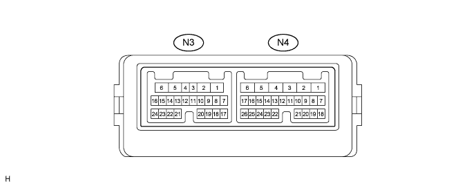
Disconnect the N3 and N4 ECU connectors.
Measure the resistance and voltage of the wire harness side connectors.
| Symbols (Terminal No.) | Wiring Color | Terminal Description | Condition | Specified Condition |
| GND (N4-1) - Body ground | W-B - Body ground | Ground | Always | Below 1 Ω |
| CPUB (N4-4) - GND (N4-1) | LG - W-B*1 B - W-B*2 | CPUB power supply | Always | 10 to 14 V |
| BDR (N4-6) - GND (N4-1) | L - W-B*1 R - W-B*2 | BDR power supply | Always | 10 to 14 V |
| SIG (N4-3) - GND (N4-1) | L - W-B*1 O - W-B*2 | IG power supply | Engine switch on (IG) | 10 to 14 V |
| TRG+ (N3-18) - GND (N4-1) | L - W-B | Lock switch signal | Lock switch not pushed | 10 kΩ or higher |
| TRG+ (N3-18) - GND (N4-1) | L - W-B | Lock switch signal | Lock switch pushed | Below 1 Ω |
Reconnect the N3 and N4 connectors.
Measure the voltage of the connector.
| Symbols (Terminal No.) | Wiring Color | Terminal Description | Condition | Specified Condition |
| OSCB (N3-7) - OSCE (N3-20) | R - G | Power source supply | Always | 10 to 14 V |
| CHECK MULTIPLEX NETWORK DOOR ECU REAR LH |

Disconnect the Q2 and Q3 ECU connectors.
Measure the resistance and voltage of the wire harness side connectors.
| Symbols (Terminal No.) | Wiring Color | Terminal Description | Condition | Specified Condition |
| GND (Q2-1) - Body ground | W-B - Body ground | Ground | Always | Below 1 Ω |
| CPUB (Q2-4) - GND (Q2-1) | BR - W-B | CPUB power supply | Always | 10 to 14 V |
| BDR (Q2-6) - GND (Q2-1) | L - W-B | BDR power supply | Always | 10 to 14 V |
| SIG (Q2-3) - GND (Q2-1) | G - W-B | IG power supply | Engine switch on (IG) | 10 to 14 V |
| TRG+ (Q3-18) - GND (Q2-1) | L - W-B | Lock switch signal | Lock switch not pushed | 10 kΩ or higher |
| TRG+ (Q3-18) - GND (Q2-1) | L - W-B | Lock switch signal | Lock switch pushed | Below 1 Ω |
Reconnect the Q2 and Q3 connectors.
Measure the voltage of the connector.
| Symbols (Terminal No.) | Wiring Color | Terminal Description | Condition | Specified Condition |
| OSCB (Q3-7) - OSCE (Q3-20) | R - G | Power source supply | Always | 10 to 14 V |
| CHECK MULTIPLEX NETWORK DOOR ECU REAR RH |
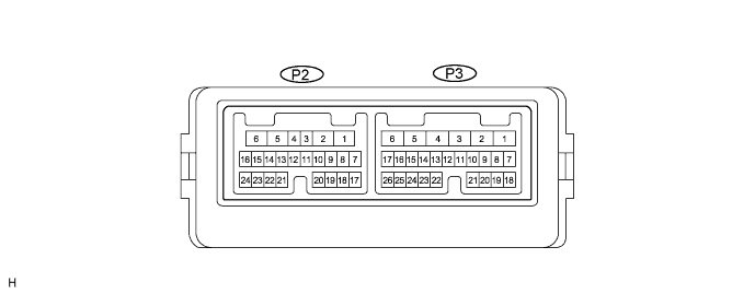
Disconnect the P2 and P3 ECU connectors.
Measure the resistance and voltage of the wire harness side connectors.
| Symbols (Terminal No.) | Wiring Color | Terminal Description | Condition | Specified Condition |
| GND (P3-1) - Body ground | W-B - Body ground | Ground | Always | Below 1 Ω |
| CPUB (P3-4) - GND (P3-1) | G - W-B | CPUB power supply | Always | 10 to 14 V |
| BDR (P3-6) - GND (P3-1) | L - W-B | BDR power supply | Always | 10 to 14 V |
| SIG (P3-3) - GND (P3-1) | L - W-B | IG power supply | Engine switch on (IG) | 10 to 14 V |
| TRG+ (P2-18) - GND (P3-1) | L - W-B | Lock switch signal | Lock switch not pushed | 10 kΩ or higher |
| TRG+ (P2-18) - GND (P3-1) | L - W-B | Lock switch signal | Lock switch pushed | Below 1 Ω |
Reconnect the P2 and P3 connectors.
Measure the voltage of the connector.
| Symbols (Terminal No.) | Wiring Color | Terminal Description | Condition | Specified Condition |
| OSCB (P2-7) - OSCE (P2-20) | R - G | Power source supply | Always | 10 to 14 V |
| CHECK NO. 1 JUNCTION BLOCK ASSEMBLY (MULTIPLEX NETWORK REAR ECU) |

Disconnect the LC and LF junction block connectors.
Measure the resistance and voltage of the wire harness side connectors.
| Symbols (Terminal No.) | Wiring Color | Terminal Description | Condition | Specified Condition |
| ECUB (LC-15) - Body ground | B - Body ground | +B power supply | Always | 10 to 14 V |
| PGND (LF-1) - Body ground | W-B - Body ground | Ground | Always | Below 1 Ω |
| SG (LC-3) - Body ground | W-B - Body ground | Ground | Always | Below 1 Ω |
