ENTRY AND START SYSTEM > Entry Unlock Function does not Operate on Driver Side Door |
| 1.CHECK MANUAL DOOR UNLOCK OPERATION |
Check that the manual door unlock function operates normally.
|
| ||||
| OK | |
| 2.READ DATA LIST (DOOR COURTESY LIGHT SWITCH) |
Check the Data List for proper functioning of the driver side door courtesy light switch.
| Item | Measurement Item / Range (Display) | Normal Condition | Diagnostic Note |
| Courtesy SW | Courtesy light switch / ON or OFF | ON: Courtesy light switch is pushed OFF: Courtesy light switch is not pushed | - |
|
| ||||
| OK | |
| 3.READ DATA LIST (LOCK POSITION SWITCH) |
Check the Data List for proper functioning of the door lock position switch.
| Item | Measurement Item / Range (Display) | Normal Condition | Diagnostic Note |
| Lock Pos SW | Door unlock detection switch signal/ ON or OFF | ON: Door is unlocked OFF: Door is locked | - |
|
| ||||
| OK | |
| 4.PERFORM ACTIVE TEST (DRIVER SIDE SELECT) |
Select the Active Test, use the intelligent tester to generate a control command, and then check that the oscillator operates.
| Item | Test Details | Diagnostic Note |
| D Select Sig | Driver side select / ON or OFF | - |
|
| ||||
| OK | |
| 5.READ DATA LIST (D TOUCH SENSOR) |
With "D Select Sig" ON, check the Data List for proper functioning of the touch sensor.
| Item | Measurement Item / Range (Display) | Normal Condition | Diagnostic Note |
| D Touch Sensor | Driver side door touch sensor / ON or OFF | ON: Sensor is touched OFF: Sensor is not touched | - |
|
| ||||
| OK | |
| 6.CHECK OPERATION OF MULTIPLEX NETWORK MASTER SWITCH ASSEMBLY |
After replacing the multiplex network master switch assembly with a normal one, check that the entry unlock function operates normally.
|
| ||||
| OK | ||
| ||
| 7.CHECK DOOR ELECTRICAL KEY OSCILLATOR FRONT |
 |
Measure the voltage of the oscillator connector.
| Tester Connection | Condition | Specified Condition |
| 4 (SEL) - Body ground | During Active Test | Below 1 V |
| 6 (SENS) - Body ground | Touch sensor is touched during Active Test | Below 1 V |
|
| ||||
| NG | |
| 8.CHECK WIRE HARNESS (DOOR ELECTRICAL KEY OSCILLATOR FRONT - DOOR ELECTRICAL KEY ANTENNA FRONT) |
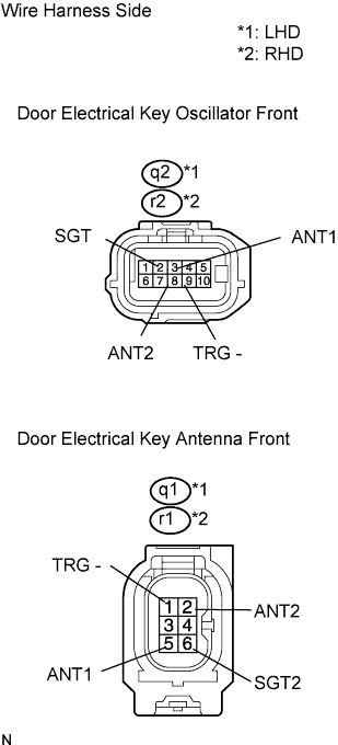 |
Disconnect the q2*1 or r2*2 oscillator connector.
Disconnect the q1*1 or r1*2 antenna connector.
Measure the resistance of the wire harness side connectors.
| Tester Connection | Specified Condition |
| q2-2 (SGT) - q1-6 (SGT2)*1 r2-2 (SGT) - r1-6 (SGT2)*2 | Below 1 Ω |
| q2-3 (ANT1) - q1-5 (ANT1)*1 r2-3 (ANT1) - r1-5 (ANT1)*2 | Below 1 Ω |
| q2-8 (ANT2) - q1-2 (ANT2)*1 r2-8 (ANT2) - r1-2 (ANT2)*2 | Below 1 Ω |
| q2-9 (TRG-) - q1-1 (TRG-)*1 r2-9 (TRG-) - r1-1 (TRG-)*2 | Below 1 Ω |
|
| ||||
| OK | |
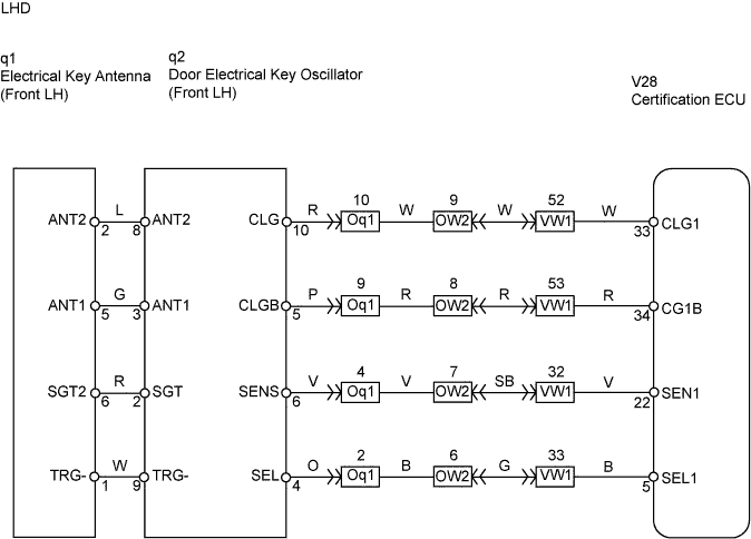
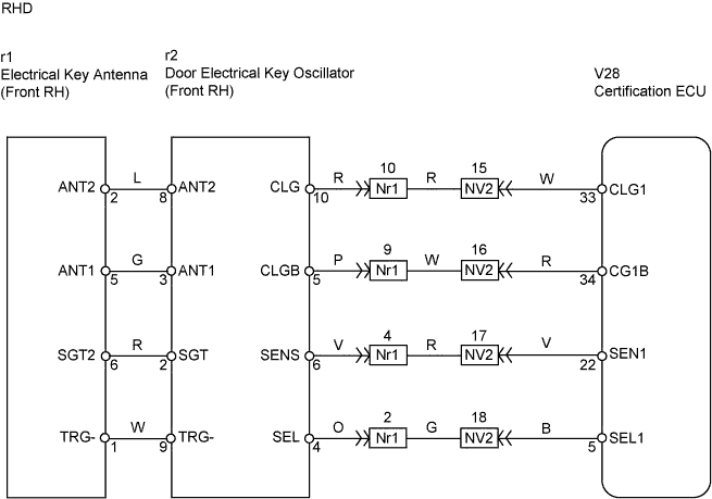
| 9.CHECK WIRE HARNESS (ECU - OSCILLATOR) |
 |
Disconnect the V28 ECU connector.
Disconnect the q2*1 or r2*2 oscillator connector.
Measure the resistance of the wire harness side connectors.
| Tester Connection | Specified Condition |
| V28-5 (SEL1) - q2-4 (SEL)*1 V28-5 (SEL1) - r2-4 (SEL)*2 | Below 1 Ω |
| V28-22 (SEN1) - q2-6 (SENS)*1 V28-22 (SEN1) - r2-6 (SENS)*2 | Below 1 Ω |
| V28-33 (CLG1) - q2-10 (CLG)*1 V28-33 (CLG1) - r2-10 (CLG)*2 | Below 1 Ω |
| V28-34 (CG1B) - q2-5 (CLGB)*1 V28-34 (CG1B) - r2-5 (CLGB)*2 | Below 1 Ω |
|
| ||||
| OK | ||
| ||
