ENTRY AND START SYSTEM > Entry Lock and Unlock Functions do not Operate on Rear Door RH |
| 1.CHECK MANUAL DOOR LOCK AND UNLOCK OPERATION |
Check that the manual door lock and unlock function operates normally.
|
| ||||
| OK | |
| 2.PERFORM ACTIVE TEST (DOOR ELECTRICAL KEY OSCILLATOR REAR RH) |
Select the Active Test, use the intelligent tester to generate a control command, and then check that the oscillator operates.
| Item | Test Details | Diagnostic Note |
| PR Transmitter | Passenger side rear transmitter ON / OFF | - |
| Item | Test Details | Diagnostic Note |
| DR Transmitter | Driver side rear transmitter ON / OFF | - |
|
| ||||
| NG | |
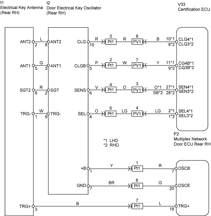
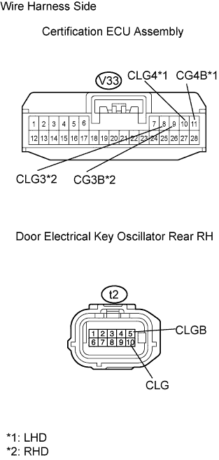
| 3.CHECK WIRE HARNESS (CERTIFICATION ECU ASSEMBLY - DOOR ELECTRICAL KEY OSCILLATOR REAR RH) |
 |
Disconnect the V33 ECU connector.
Disconnect the t2 oscillator connector.
Measure the resistance of the wire harness side connectors.
| Tester Connection | Specified Condition |
| V33-10 (CLG4) - t2-10 (CLG)*1 V33-8 (CLG3) - t2-10 (CLG)*2 | Below 1 Ω |
| V33-11 (CG4B) - t2-5 (CLGB)*1 V33-9 (CG3B) - t2-5 (CLGB)*2 | Below 1 Ω |
|
| ||||
| OK | |
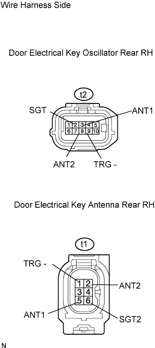
| 4.CHECK WIRE HARNESS (DOOR ELECTRICAL KEY OSCILLATOR REAR RH - DOOR ELECTRICAL KEY ANTENNA REAR RH) |
 |
Disconnect the t2 oscillator connector.
Disconnect the t1 antenna connector.
Measure the resistance of the wire harness side connectors.
| Tester Connection | Specified Condition |
| t2-2 (SGT) - t1-6 (SGT2) | Below 1 Ω |
| t2-3 (ANT1) - t1-5 (ANT1) | Below 1 Ω |
| t2-8 (ANT2) - t1-2 (ANT2) | Below 1 Ω |
| t2-9 (TRG-) - t1-1 (TRG-) | Below 1 Ω |
|
| ||||
| OK | |
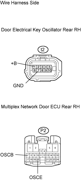
| 5.CHECK WIRE HARNESS (DOOR ELECTRICAL KEY OSCILLATOR REAR RH - MULTIPLEX NETWORK DOOR ECU REAR RH) |
 |
Disconnect the t2 oscillator connector.
Disconnect the P2 ECU connector.
Measure the resistance of the wire harness side connectors.
| Tester Connection | Specified Condition |
| t2-1 (+B) - P2-7 (OSCB) | Below 1 Ω |
| t2-7 (GND) - P2-20 (OSCE) | Below 1 Ω |
|
| ||||
| OK | |
| 6.CHECK WIRE HARNESS (DOOR ELECTRICAL KEY ANTENNA REAR RH - MULTIPLEX NETWORK DOOR ECU REAR RH) |
 |
Disconnect the t1 antenna connector.
Disconnect the P2 ECU connector.
Measure the resistance of the wire harness side connectors.
| Tester Connection | Specified Condition |
| t1-3 (TRG+) - P2-18 (TRG+) | Below 1 Ω |
|
| ||||
| OK | |
| 7.CHECK OPERATION OF ELECTRICAL KEY ANTENNA REAR RH |
After replacing the electrical key antenna rear RH with a normal one, check that the entry lock and unlock functions operate normally.
|
| ||||
| OK | |
| 8.CHECK OPERATION OF DOOR ELECTRICAL KEY OSCILLATOR REAR RH |
After replacing the door electrical key oscillator rear RH with a normal one, check that the entry lock and unlock functions operate normally.
|
| ||||
| OK | ||
| ||
