CAN COMMUNICATION SYSTEM > TERMINALS OF ECU |
| JUNCTION CONNECTOR (D-CAN J/C, P-CAN J/C), LHD. |
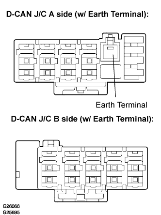 |
D-CAN J/C.
| D-CAN J/C connectors (A side, w/ earth terminal) | Color (CAN-H Side) | Color (CAN-L Side) |
| Skid control ECU/ Skid control ECU with actuator | P | O |
| ECM | BR | GR |
| CAN main bus line (bus line to connect - D-CAN and P-CAN J/C ) | B | W |
| Yaw rate sensor | R | W |
| D-CAN J/C connectors (B side, w/o earth terminal) | Color (CAN-H Side) | Color (CAN-L Side) |
| Distance control ECU | BR | Y |
| Seat belt control ECU | P | W |
| DLC3 | L | LG |
| Steering angle sensor | R | W |
 |
P-CAN J/C.
| P-CAN J/C A Side (w/ Earth Terminal) | Color (CAN-H Side) | Color (CAN-L Side) |
| Clearance warning ECU | P | LG |
| Network gateway ECU | L | Y |
| Television camera ECU | BR | GR |
| P-CAN J/C B Side (w/o Earth Terminal) | Color (CAN-H Side) | Color (CAN-L Side) |
| CAN bus line (bus line connect P-CAN J/C and D-CAN J/C) | B | W |
| Steering control ECU | R | W |
| Absorber control ECU | BR | Y |
| Power steering ECU | P | V |
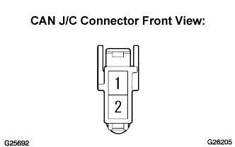 |
The terminals on connectors for the CAN J/C.
| Terminal | Terminal symbol |
| 1 | CANH |
| 1 | CANL |
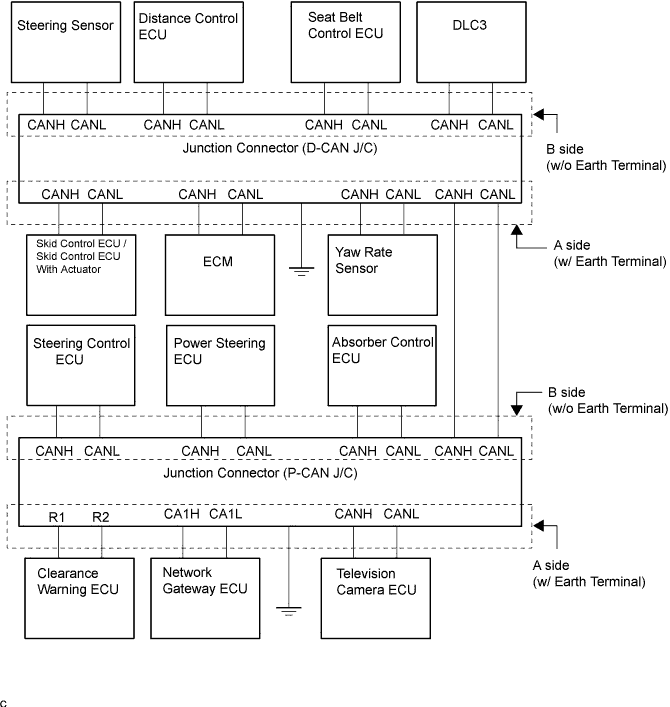
Wiring diagram for identifying CAN J/C connectors.
| JUNCTION CONNECTOR (D-CAN J/C, P-CAN J/C), RHD. |
|
D-CAN J/C.
| D-CAN J/C connectors (A side, w/ earth terminal) | Color (CAN-H Side) | Color (CAN-L Side) |
| Skid control ECU/ Skid control ECU with actuator | BR | GR |
| Network gateway ECU | L | Y |
| Steering sensor | R | W |
| Yaw rate sensor | P | LG |
| D-CAN J/C connectors (B side, w/o earth terminal) | Color (CAN-H Side) | Color (CAN-L Side) |
| Distance control ECU | P | V |
| Absorber control ECU | BR | Y |
| DLC3 | L | LG |
| CAN main bus line (bus line to connect - D-CAN and P-CAN J/C ) | B | W |
|
P-CAN J/C.
| P-CAN J/C A Side (w/ Earth Terminal) | Color (CAN-H Side) | Color (CAN-L Side) |
| Power steering ECU | P | O |
| ECM | BR | GR |
| Steering control ECU | R | W |
| P-CAN J/C B Side (w/o Earth Terminal) | Color (CAN-H Side) | Color (CAN-L Side) |
| Seat belt control ECU | P | W |
| Television camera ECU | BR | Y |
| Clearance warning ECU | L | Y |
| CAN bus line (bus line connect P-CAN J/C and D-CAN J/C) | B | W |
|
The terminals on connectors for the CAN J/C.
| Terminal | Terminal symbol |
| 1 | CANH |
| 1 | CANL |
Wiring diagram for identifying CAN J/C connectors.

| DLC3 |
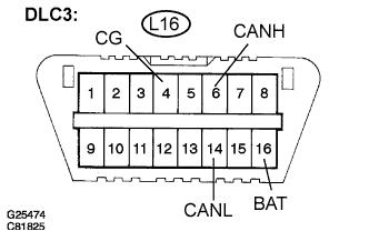 |
Measure the resistance according to the value(s) in the table below.
| Terminals | Wiring Color | Condition | Specified Condition |
| L16-6 (CANH) - L16-14 (CANL) | L - LG | Engine Switch off | 54 to 69 Ω |
| L16-6 (CANH) - L16-4 (CG) | L - W-B | Engine Switch off | 1 kΩ or more |
| L16-14 (CANL) - L16-4 (CG) | LG - W-B | Engine Switch off | 1 kΩ or more |
| L16-6 (CANH) - L16-16 (BAT) | L - W-B | Engine Switch off | 1 MΩ or more |
| L16-14 (CANL) - L16-16 (BAT) | LG - O | Engine Switch off | 1 MΩ or more |
| SKID CONTROL ECU |
 |
Measure the resistance according to the value(s) in the table below (3UZ-FE).
| Terminals | Wiring Color | Condition | Specified Condition |
| A15-9 (CANH) - A15-25 (CANL) | P - O | Engine Switch off | 54 to 69 Ω |
| A15-9 (CANH) - A15-32 (GND4) | P - W-B | Engine Switch off | 1 kΩ or more |
| A15-22 (CANL) - A15-32 (GND4) | O - W-B | Engine Switch off | 1 kΩ or more |
| A15-9 (CANH) - A15-2 (BS2) | P - G | Engine Switch off | 1 MΩ or more |
| A15-22 (CANL) - A15-2 (BS2) | O - G | Engine Switch off | 1 MΩ or more |
| SKID CONTROL ECU WITH ACTUATOR |
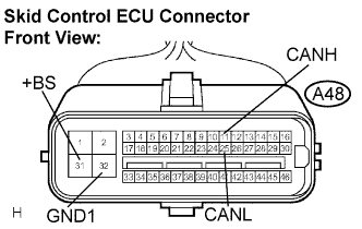 |
Measure the resistance according to the value(s) in the table below (3GR-FSE,3GR-FE).
| Terminals | Wiring Color | Condition | Specified Condition |
| A48-11 (CANH) - A48-25 (CANL) | P - O | Engine Switch off | 54 to 69 Ω |
| A48-11 (CANH) - A48-32 (GND1) | P - W-B | Engine Switch off | 1 kΩ or more |
| A48-25 (CANL) - A48-32 (GND1) | O - W-B | Engine Switch off | 1 kΩ or more |
| A48-11 (CANH) - A48-31 (+BS) | P - R | Engine Switch off | 1 MΩ or more |
| A48-25 (CANL)- A48-32 (+BS) | O - G | Engine Switch off | 1 MΩ or more |
| STEERING SENSOR |
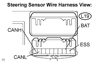 |
Measure the resistance according to the value(s) in the table below.
| Terminals | Wiring Color | Condition | Specified Condition |
| L19-10 (CANH) - L19-9 (CANL) | R - W | Engine Switch off | 54 to 69 Ω |
| L19-10 (CANH) - L19-2 (ESS) | R - W-B | Engine Switch off | 1 kΩ or more |
| L19-9 (CANL) - L19-2 (ESS) | W - W-B | Engine Switch off | 1 kΩ or more |
| L19-10 (CANH) - L19-3 (BAT) | R - LG | Engine Switch off | 1 MΩ or more |
| L19-9 (CANL) - L19-3 (BAT) | W - LG | Engine Switch off | 1 MΩ or more |
| YAW RATE SENSOR |
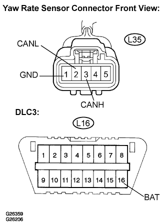 |
Measure the resistance according to the value(s) in the table below.
| Terminals | Wiring Color | Condition | Specified Condition |
| L35-3 (CANH) - L35-2 (CANL) | R - W | Engine Switch off | 54 to 69 Ω |
| L35-3 (CANH) - L35-1 (GND) | R - W-B | Engine Switch off | 1 kΩ or more |
| L35-2 (CANL) - L35-1 (GND) | W - W-B | Engine Switch off | 1 kΩ or more |
| L35-3 (CANH) - L16-16 (BAT) | R - O | Engine Switch off | 1 MΩ or more |
| L35-2 (CANL) - L16-16 (BAT) | W - O | Engine Switch off | 1 MΩ or more |
| DISTANCE CONTROL ECU |
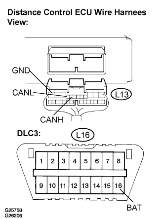 |
Measure the resistance according to the value(s) in the table below.
| Terminals | Wiring Color | Condition | Specified Condition |
| L13-8 (CANH) - L13-9 (CANL) | BR - GR | Engine Switch off | 54 to 69 Ω |
| L13-8 (CANH) - L13-12 (GND) | BR - G | Engine Switch off | 1 kΩ or more |
| L13-9 (CANL) - L13-12 (GND) | GR - G | Engine Switch off | 1 kΩ or more |
| L13-8 (CANH) - L16-16 (BAT) | BR - O | Engine Switch off | 1 MΩ or more |
| L13-9 (CANL) - L16-16 (BAT) | GR - O | Engine Switch off | 1 MΩ or more |
| TELEVISION CAMERA ECU |
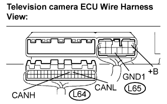 |
Measure the resistance according to the value(s) in the table below.
| Terminals | Wiring Color (LHD) | Wiring Color (RHD) | Condition | Specified Condition |
| L64-8 (CANH) - L64-7 (CANL) | BR - GR | BR - Y | Engine Switch off | 54 to 69 Ω |
| L64-8 (CANH) - L64-8 (GND1) | BR - W-B | BR - W-B | Engine Switch off | 1 kΩ or more |
| L64-7 (CANL) - L65-8 (GND1) | GR - W-B | Y - W-B | Engine Switch off | 1 kΩ or more |
| L64-8 (CANH) - L65-1 (+B) | BR - L | BR - L | Engine Switch off | 1 MΩ or more |
| L64-7 (CANL) - L65-1 (+B) | GR - L | Y - L | Engine Switch off | 1 MΩ or more |
| ECM |
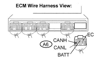 |
Measure the resistance according to the value(s) in the table below.
| Terminals | Wiring Color | Condition | Specified Condition |
| A6-25 (CANH) - A6-24 (CANL) | BR - GR | Engine Switch off | 54 to 69 Ω |
| A6-25 (CANH) - A6-2 (EC) | BR - W-B | Engine Switch off | 1 kΩ or more |
| A6-24 (CANL) - A6-2 (EC) | GR - W-B | Engine Switch off | 1 kΩ or more |
| A6-25 (CANH) - A6-4 (BATT) | BR - L | Engine Switch off | 1 MΩ or more |
| A6-24 (CANL) - A6-4 (BATT) | GR - L | Engine Switch off | 1 MΩ or more |
| SEAT BELT CONTROL ECU |
 |
Measure the resistance according to the value(s) in the table below.
| Terminals | Wiring Color | Condition | Specified Condition |
| W30-4 (CANH) - W30-6 (CANL) | P - W | Engine Switch off | 54 to 69 Ω |
| W30-4 (CANH) - W30-18 (PGND) | P - W-B | Engine Switch off | 1 kΩ or more |
| W30-6 (CANL) - W30-18 (PGND) | W - W-B | Engine Switch off | 1 kΩ or more |
| W30-4 (CANH) - W30-9 (+B) | P - L | Engine Switch off | 1 MΩ or more |
| W30-6 (CANL) - W30-9 (+B) | W - L | Engine Switch off | 1 MΩ or more |
| POWER STEERING ECU |
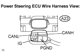 |
Measure the resistance according to the value(s) in the table below.
| Terminals | Wiring Color (LHD) | Wiring Color (RHD) | Condition | Specified Condition |
| A23-2 (CANH) - A23-3 (CANL) | P - V | P - O | Engine Switch off | 54 to 69 Ω |
| A23-2 (CANH) - A23-5 (PGND) | P - B | P - B | Engine Switch off | 1 kΩ or more |
| A23-3 (CANL) - A23-5 (PGND) | V - B | O - B | Engine Switch off | 1 kΩ or more |
| A23-2 (CANH) - A23-9 (IG) | P - B-Y | P - B-Y | Engine Switch on (IG) | 1 MΩ or more |
| A23-3 (CANL) - A23-9 (IG) | V - B-Y | P - B-Y | Engine Switch on (IG) | 1 MΩ or more |
| STEERING CONTROL ECU |
 |
Measure the resistance according to the value(s) in the table below.
| Terminals | Wiring Color | Condition | Specified Condition |
| L70-9 (CANH) - L70-20 (CANL) | W - R | Engine Switch off | 54 to 69 Ω |
| L70-9 (CANH) - A42-7 (PGND) | W - W-B | Engine Switch off | 1 kΩ or more |
| L70-20 (CANL) - A42-7 (PGND) | R - W-B | Engine Switch off | 1 kΩ or more |
| L70-9 (CANH) - A42-10 (+B1) | W - GR | Engine Switch off | 1 MΩ or more |
| L70-20 (CANL) - A42-10 (+B1) | R - GR | Engine Switch off | 1 MΩ or more |
| CLEARANCE WARNING ECU |
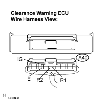 |
Measure the resistance according to the value(s) in the table below.
| Terminals | Wiring Color (LHD) | Wiring Color (RHD) | Condition | Specified Condition |
| A40-23 (R1) - A40-24 (R2) | P - LG | L -Y | Engine Switch off | 54 to 69 Ω |
| A40-23 (R1) - A40-27 (E) | P - W-B | L - W-B | Engine Switch off | 1 kΩ or more |
| A40-24 (R2) - A40-27 (E) | LG - W-B | Y -W-B | Engine Switch off | 1 kΩ or more |
| A40-23 (R1) - A40-8 (IG) | P - G-Y | L - G-Y | Engine Switch off | 1 MΩ or more |
| A40-24 (R2) - A40-8 (IG) | LG - G-Y | Y - G-Y | Engine Switch off | 1 MΩ or more |
| NETWORK GATEWAY ECU |
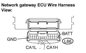 |
Measure the resistance according to the value(s) in the table below.
| Terminals | Wiring Color | Condition | Specified Condition |
| L66-17(CA1H)-L66-18(CA1L) | L - Y | Engine Switch off | 54 to 69 Ω |
| L66-17 (CA1H) - L66-24 (GND) | L - W-B | Engine Switch off | 1 kΩ or more |
| L66-18 (CA1L) - L66-24 (GND) | Y - W-B | Engine Switch off | 1 kΩ or more |
| L66-17 (CA1H) - L66-10 (BATT) | L- G | Engine Switch off | 1 MΩ or more |
| L66-18 (CA1L) - L66-10 (BATT) | Y - G | Engine Switch off | 1 MΩ or more |
| ABSORBER CONTROL ECU |
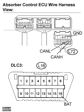 |
Measure the resistance according to the value(s) in the table below.
| Terminals | Wiring Color | Condition | Specified Condition |
| L72-7 (CANH) - L72-8 (CANL) | R - Y | Engine Switch off | 54 to 69 Ω |
| L72-7 (CANH) - L72-4 (GND) | R - W-B | Engine Switch off | 1 kΩ or more |
| L72-8 (CANL) - L72-4 (GND) | Y - W-B | Engine Switch off | 1 kΩ or more |
| L72-7 (CANH) - L16-16 (BAT) | R - L | Engine Switch off | 1 MΩ or more |
| L72-8 (CANL) - L16-16 (BAT) | Y - L | Engine Switch off | 1 MΩ or more |
