DTC    C1241/41    Low Battery Positive Voltage

for Preparation Click here


DESCRIPTION

If a malfunction is detected in the power supply circuit, the skid control ECU (housed in the actuator assembly) outputs the DTC and prohibits operation with the fail-safe function.
This DTC is stored when the IG1 terminal voltage deviates from the DTC detecting condition due to a malfunction in the power supply or charging circuit such as the battery or alternator circuit, etc.
The DTC is cancelled when the IG1 terminal voltage returns to normal.

DTC No.
DTC Detecting Condition
Trouble Area
C1241/41
When any of the following is detected:
  1. At a vehicle speed of 2 mph (3 km/h) or more, the IG1 terminal voltage is 9.5 V or less for 10 seconds or more.
  2. When the solenoid relay remains ON and the IG1 terminal voltage is 9.5 V or less, the relay contact is open for 0.2 seconds or more.
  3. With the IG1 terminal voltage 9.5 V or less, the vehicle speed sensor power supply decreases for 60 seconds or more.
  1. Battery
  2. Charging system
  3. Power source circuit
  4. Internal power supply circuit of the skid control ECU

WIRING DIAGRAM


C109390E01


INSPECTION PROCEDURE

NOTICE:
When replacing the ABS and TRACTION actuator assembly, perform zero point calibration (Click here).

1.INSPECT FUSE (ECU-IG LH FUSE)
  1. Remove the ECU-IG LH fuse from the cowl side J/B LH.

  1. Measure the resistance according to the value(s) in the table below.

    Resistance:

    Tester Connection
    Specified Condition
    ECU-IG LH fuse
    Below 1 Ω (Continuity)


NG
REPLACE FUSE (ECU-IG LH FUSE)
OK


2.INSPECT BATTERY
  1. Check the battery voltage.

    Voltage:
    10 to 14 V


NG
INSPECT CHARGING SYSTEM
OK


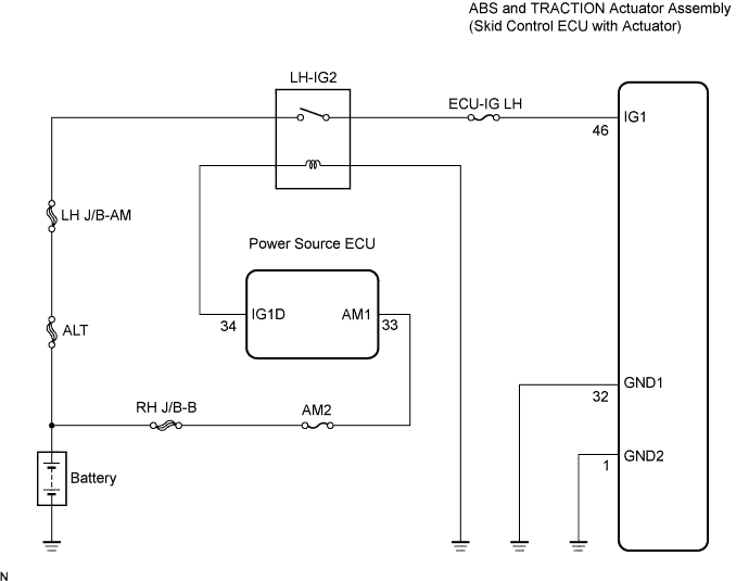
3.INSPECT SKID CONTROL ECU TERMINAL VOLTAGE (IG1 TERMINAL)


    F049362E14
  1. Disconnect the skid control ECU connector.

  1. Turn the engine switch on (IG).

  1. Measure the voltage according to the value(s) in the table below.

    Voltage:
    Tester Connection
    Condition
    Specified Condition
    A48-46 (IG1) - Body ground
    Engine switch on (IG)
    10 to 14 V


NG
REPAIR OR REPLACE HARNESS OR CONNECTOR (IG1 CIRCUIT)
OK


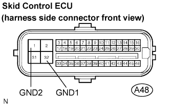
4.INSPECT SKID CONTROL ECU (GND TERMINAL CONTINUITY)


    F049362E15
  1. Disconnect the skid control ECU connector.

  1. Measure the resistance according to the value(s) in the table below.

    Resistance:
    Tester Connection
    Specified Condition
    A48-32 (GND1) - Body ground
    Below 1 Ω
    A48-1 (GND2) - Body ground
    Below 1 Ω


NG
REPAIR OR REPLACE HARNESS OR CONNECTOR (GND CIRCUIT)
OK


5.RECONFIRM DTC
  1. Clear the DTC (Click here).

  1. Turn the engine switch on (IG).

  1. Check that the same DTC is recorded (Click here).

    Result:

    Condition
    Proceed To
    DTC (C1241/41) is not output
    A
    DTC (C1241/41) is output
    B

    HINT:
    If troubleshooting has been carried out according to the problem symptoms table, refer back to the table and proceed to the next step (Click here).


B
REPLACE ABS AND TRACTION ACTUATOR ASSEMBLY
A

END