DTC B1297 Clearance Sonar ECU Communication Stop |
| DTC No. | DTC Detection Condition | Trouble Area |
| B1297 | Clearance warning ECU assembly communication stops |
|
| 1.CHECK OPERATION |
Turn the engine switch on (IG) and the clearance sonar main switch ON. Check that the combination meter displays the graphic of the system check operation for approximately 2 seconds as it checks for an open circuit and a malfunction in the sensor. Also, check that the buzzer emits a sound for approximately 1 second.
|
| ||||
| OK | ||
| ||
| 2.INSPECT FUSE (LH-IG) |
Remove the LH-HG fuse from the junction block.
Measure the resistance of the wire harness side connector.
|
| ||||
| OK | |
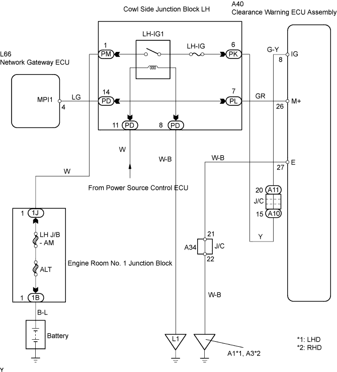
| 3.CHECK WIRE HARNESS (CLEARANCE SONAR ECU - BODY GROUND) |
 |
Disconnect the A40 ECU connector.
Measure the voltage and resistance of the wire harness side connector.
| Tester Connection | Condition | Specified Condition |
| A40-8 (IG) - Body ground | Engine switch off→on (IG) | 0 V → 10 to 14 V |
| Tester Connection | Condition | Specified Condition |
| A40-26 (M+) - Body ground | Constant | Below 1 Ω |
|
| ||||
| OK | |
| 4.CHECK RESISTANCE OF COMMUNICATION LINE |
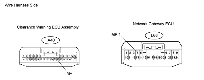
Disconnect the A40 ECU connector.
Disconnect the L66 ECU connector.
Measure the resistance between the wire harness side connectors.
| Tester Connection | Specified Condition |
| A40-26 (M+) - L66-4 (MPI1) | Below 1 Ω |
|
| ||||
| OK | ||
| ||
