ELECTRIC STEERING LOCK > Power Source Circuit |

| 1.CHECK HARNESS AND CONNECTOR (STEERING LOCK ACTUATOR ASSEMBLY - BODY GROUND) |
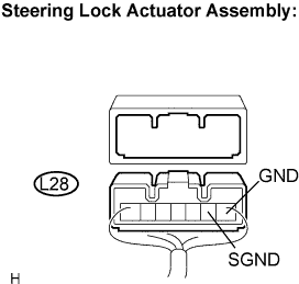 |
Disconnect the L28 connector from the steering lock actuator assembly.
Measure the resistance according to the value(s) in the table below.
| Tester connection (Symbols) | Condition | Specified condition |
| L28-1 (GND) - Body ground | Always | Below 1 Ω |
| L28-2 (SGND) - Body ground | Always | Below 1 Ω |
|
| ||||
| OK | |
| 2.CHECK HARNESS AND CONNECTOR (STEERING LOCK ACTUATOR ASSEMBLY - BATTERY) |
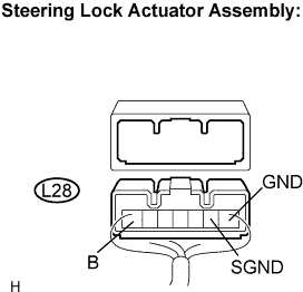 |
Measure the voltage according to the value(s) in the table below.
| Tester connection (Symbols) | Condition | Specified condition |
| L28-7 (B) - L28-1 (GND) | Always | 10 to 14 V |
| L28-7 (B) - L28-2 (SGND) | Always | 10 to 14 V |
|
| ||||
| NG | ||
| ||
