WIRELESS DOOR LOCK CONTROL SYSTEM > TERMINALS OF ECU |
| CHECK COWL SIDE JUNCTION BLOCK RH ASSEMBLY (MULTIPLEX NETWORK BODY ECU) |
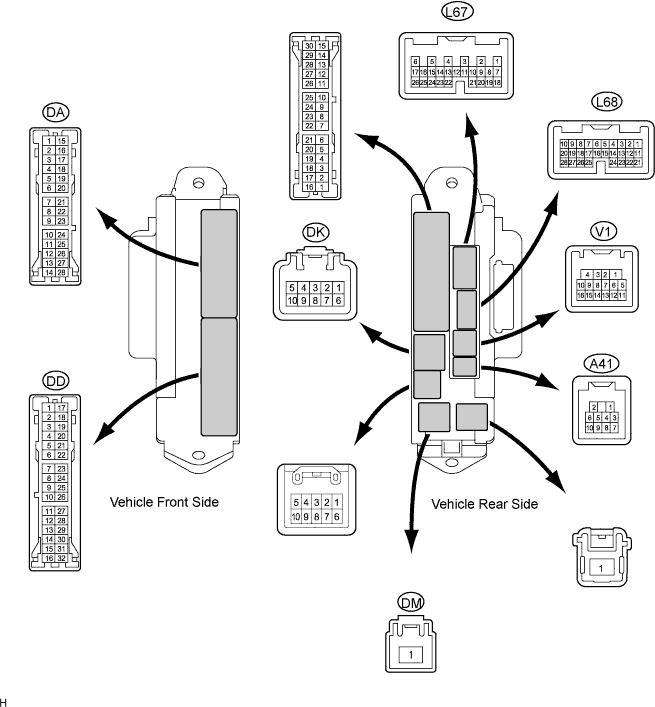
Disconnect the DA, DD, DK and DM junction block connectors.
Disconnect the L68 and V1 ECU connectors.
Measure the resistance and voltage of the wire harness side connectors.
| Symbols (Terminal No.) | Wiring Color | Terminal Description | Condition | Specified Condition |
| BECU (DK-5) - GND2 (DD-7) | G-R - W-B | BECU power supply | Always | 10 to 14 V |
| ACC (DM-1) - GND2 (DD-7) | B - W-B | ACC power supply | Always | 10 to 14 V |
| IG (DM-1) - GND2 (DD-7) | B - W-B | IG power supply | Always | 10 to 14 V |
| DCTY (V1-14) - Body ground | R - Body ground | Driver side door courtesy light switch input | Driver side door open | Below 1 Ω |
| DCTY (V1-14) - Body ground | R - Body ground | Driver side door courtesy light switch input | Driver side door closed | 10 kΩor higher |
| PCTY (L68-23) - Body ground | R - Body ground | Passenger side door courtesy light switch input | Passenger side door open | Below 1 Ω |
| PCTY (L68-23) - Body ground | R - Body ground | Passenger side door courtesy light switch input | Passenger side door closed | 10 kΩor higher |
| RCTY (V1-16) - Body ground | L - Body ground | Rear RH side door courtesy light switch input | Rear RH side door open | Below 1 Ω |
| RCTY (V1-16) - Body ground | L - Body ground | Rear RH side door courtesy light switch input | Rear RH side door closed | 10 kΩor higher |
| LCTY (DA-11) - Body ground | G - Body ground | Rear LH side door courtesy light switch input | Rear LH side door open | Below 1 Ω |
| LCTY (DA-11) - Body ground | G - Body ground | Rear LH side door courtesy light switch input | Rear LH side door closed | 10 kΩor higher |
| GND2 (DD-7) - Body ground | W-B - Body ground | Ground | Always | Below 1 Ω |
| GND2 (DA-5) - Body ground | W-B - Body ground | Ground | Always | Below 1 Ω |
Reconnect the DA, DD, DK and DM junction connectors.
Reconnect the L68 and V1 ECU connectors.
Measure the voltage of the wire harness side connectors.
| Symbols (Terminal No.) | Wiring Color | Terminal Description | Condition | Specified Condition |
| HAZ (L67-2) - Body ground | O - Body ground | Hazard warning light drive | Answer-back ON | Pulse generation |
| HAZ (L67-2) - Body ground | O - Body ground | Hazard warning light drive | Answer-back OFF | 10 to 14 V |
| BZR (A41-2) - Body ground | G - Body ground | Wireless warning buzzer drive | Answer-back ON | Pulse generation |
| BZR (A41-2) - Body ground | G - Body ground | Wireless warning buzzer drive | Answer-back OFF | 10 to 14 V |
| CHECK CERTIFICATION ECU ASSEMBLY |

Disconnect the V28 ECU connector.
Measure the voltage and resistance of the wire harness side connector.
| Symbols (Terminal No.) | Wiring Color | Terminal Description | Condition | Specified Condition |
| +B1 (V28-1) - E (V28-17) | G - W-B | Battery power supply | Always | 10 to 14 V |
| IG (V28-18) - E (V28-17) | B - W-B | IG power supply | Engine switch on (IG) | 10 to 14 V |
| IG (V28-18) - E (V28-17) | B - W-B | IG power supply | Engine switch off | Below 1 V |
| E (V28-17) - Body ground | W-B - Body ground | Ground | Always | Below 1 Ω |
Reconnect the V28 ECU connector.
Measure the voltage of the connector.
| Symbols (Terminal No.) | Wiring Color | Terminal Description | Condition | Specified Condition |
| RSS1 (V28-39) - E (V28-17) | O - W-B | Door control receiver output signal | Engine switch off, all doors closed and transmitter switch not pressed | 10 to 14 V |
| RSS1 (V28-39) - E (V28-17) | O - W-B | Door control receiver output signal | Engine switch off, all doors closed and transmitter switch pressed | Below 1 V |
| RDA (V28-38) - E (V28-17) | LG - W-B | Door control receiver output signal | Engine switch off, all doors closed and transmitter switch not pressed | 10 to 14 V |
| RDA (V28-38) - E (V28-17) | LG - W-B | Door control receiver output signal | Engine switch off, all doors closed and transmitter switch pressed | Pulse generation |
