WIRELESS DOOR LOCK CONTROL SYSTEM > Only Wireless Control Function is inoperative |
| 1.CHECK WIRELESS DOOR LOCK |
|
| ||||
| OK | ||
| ||
| 2.CHECK THAT TRANSMITTER LED ILLUMINATES |
Check that the transmitter's LED illuminates 3 times when the switch is pressed 3 times.
|
| ||||
| OK | |
| 3.CHECK WIRELESS DOOR LOCK CONTROL FUNCTIONS (STANDARD OPERATION) |
Check standard LOCK/UNLOCK switch operation.
|
| ||||
| OK | ||
| ||
| 4.REPLACE TRANSMITTER BATTERY |
After replacing the transmitter battery, check that the doors can be locked and unlocked by using the transmitter LOCK/UNLOCK switch.
|
| ||||
| OK | ||
| ||
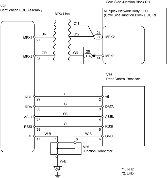
| 5.CHECK CERTIFICATION ECU ASSEMBLY |
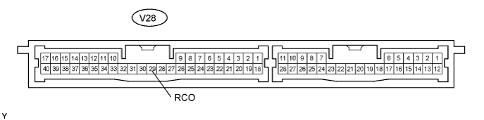
Reconnect the V28 ECU connector.
Measure the voltage of the wire harness side connector.
| Tester Connection | Specified Condition |
| V28-29 (RCO) - Body ground | 4.6 to 5.4 V |
|
| ||||
| OK | |
| 6.CHECK WIRE HARNESS (CERTIFICATION ECU - DOOR CONTROL RECEIVER AND BODY GROUND) |
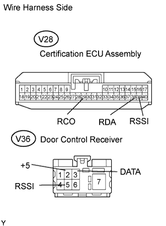 |
Disconnect the V36 receiver connector.
Disconnect the V28 ECU connector.
Measure the resistance of the wire harness side connectors.
| Tester Connection | Specified Condition |
| V28-39 (RSSI) - V36-5 (RSSI) | Below 1 Ω |
| V28-38 (RDA) - V36-3 (DATA) | Below 1 Ω |
| V28-29 (RCO) - V36-2 (+5) | Below 1 Ω |
| V28-39 (RSSI) - Body ground | 10 KΩ or higher |
| V28-38 (RDA) - Body ground | 10 KΩ or higher |
|
| ||||
| OK | |
| 7.CHECK DOOR CONTROL RECEIVER (OUTPUT) |
 |
Reconnect the V36 receiver connector.
Measure the voltage between the terminal of the connector and body ground.
| Tester Connection | Condition | Specified Condition |
| V36-3 (DATA) - Body ground | Engine switch off, all doors closed and transmitter switch not pressed | 10 to 14 V |
| V36-3 (DATA) - Body ground | Engine switch off, all doors closed and transmitter switch pressed | Pulse generation |
|
| ||||
| OK | ||
| ||
