POWER TILT AND POWER TELESCOPIC STEERING COLUMN > Actuator Power Source Circuit |
| 1.INSPECT FUSE (TI & TE) |
Remove the TI & TE fuse from the cowl side J/B RH.
Check the continuity of the TI & TE fuse.
|
| ||||
| OK | |
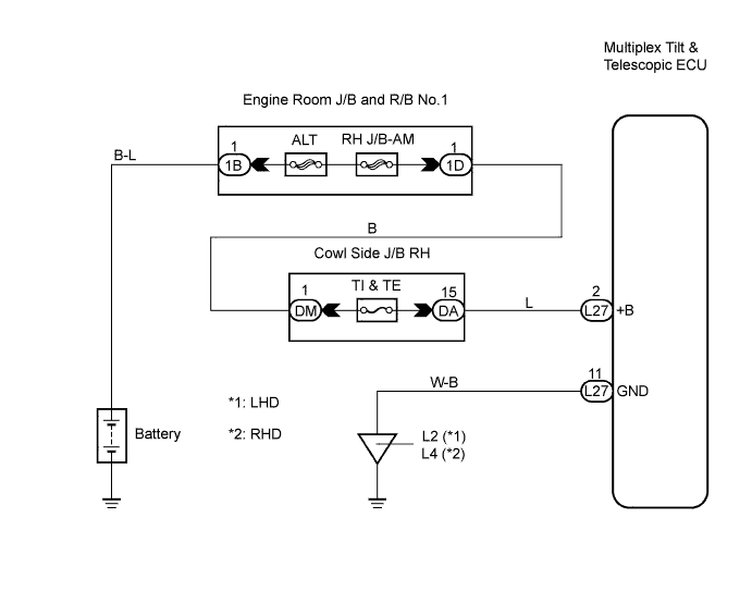
| 2.CHECK HARNESS AND CONNECTOR (MULTIPLEX TILT & TELESCOPIC ECU - BATTERY) |
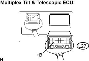 |
Disconnect the L27 connector from the multiplex tilt & telescopic ECU.
Measure the voltage according to the value(s) in the table below.
| Tester connection (Terminal No.) | Condition | Specified value |
| +B (L27-2) - Body ground | Always | 10 to 14 V |
|
| ||||
| OK | |
| 3.CHECK HARNESS AND CONNECTOR (MULTIPLEX TILT & TELESCOPIC ECU - BODY GROUND) |
 |
Measure the resistance according to the value(s) in the table below.
| Tester connection (Terminal No.) | Condition | Specified value |
| GND (L27-11) - Body ground | Always | Below 1 Ω |
|
| ||||
| OK | ||
| ||
| 4.CHECK HARNESS AND CONNECTOR (MULTIPLEX TILT & TELESCOPIC ECU - COWL SIDE J/B RH) |
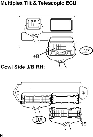 |
Disconnect the DA connector from the cowl side J/B RH.
Measure the resistance according to the value(s) in the table below.
| Tester condition (Terminal No.) | Condition | Specified value |
| +B (L27-2) - DA-15 | Always | Below 1 Ω |
| +B (L27-2) - Body ground | Always | 10 kΩ or higher |
|
| ||||
| OK | ||
| ||
