LUGGAGE COMPARTMENT DOOR OPENER AND CLOSER SYSTEM > Driver Side J/B ECU Power Source Circuit |
| 1.INSPECT FUSE (TRK OPN, MPX-B, D/C CUT) |
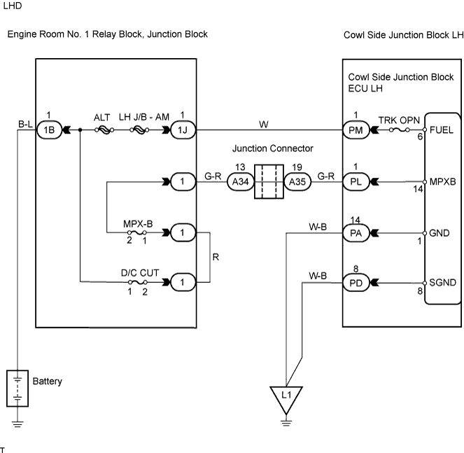
Remove the TRK OPN fuse from the cowl side junction block ECU LH.
Remove the MPX-B and D/C CUT fuses from the engine room No. 1 relay block.
Measure the resistance of the fuses.
|
| ||||
| OK | |
| 2.CHECK WIRE HARNESS (COWL SIDE JUNCTION BLOCK LH - BATTERY AND BODY GROUND) |

Disconnect the PM, PL, PA and PD junction block connectors.
Measure the voltage and resistance of the wire harness side connectors.
| Tester Connection | Specified Condition |
| PM-1 (FUEL) - Body ground | 10 to 14 V |
| PL-1 (MPX-B) - Body ground | 10 to 14 V |
| Tester Connection | Specified Condition |
| PA-14 (GND) - Body ground | Below 1 Ω |
| PD-8 (SGND) - Body ground | Below 1 Ω |
|
| ||||
| OK | ||
| ||
| 1.INSPECT FUSE (MPX-B, D/C CUT) |
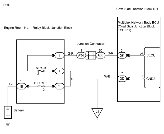
Remove the MPX-B and D/C CUT fuses from the engine room No. 1 relay block.
Measure the resistance of the fuses.
|
| ||||
| OK | |
| 2.CHECK WIRE HARNESS (COWL SIDE JUNCTION BLOCK RH - BATTERY AND BODY GROUND) |
 |
Disconnect the DK and DD junction block connectors.
Measure the voltage and resistance of the wire harness side connectors.
| Tester Connection | Specified Condition |
| DK-5 (BECU) - Body ground | 10 to 14 V |
| Tester Connection | Specified Condition |
| DD-7 (GND2) - Body ground | Below 1 Ω |
|
| ||||
| OK | ||
| ||
