DTC B1461/61 Emission Gas NOx Sensor Circuit |
| DTC No. | DTC Detection Condition | Trouble Area |
| B1461/61 | Open or short in emission gas NOx sensor circuit |
|
| 1.INSPECT FUSE (LH-IG) |
Remove the LH-IG fuse from the cowl side junction block LH .
Measure the resistance of the fuse.
| Tester Item | Condition | Specified Condition |
| LH-IG fuse | Always | Below 1 Ω |
|
| ||||
| OK | |
| 2.READ VALUE OF INTELLIGENT TESTER |
Connect the intelligent tester to the DLC3.
Turn the engine switch on (IG) and push the intelligent tester main switch on.
Select the item below in the Data List, and read the display on the intelligent tester.
| Item | Measure Item / Display (Range) | Normal Condition | Diagnostic Note |
| Emission Gas Nox Sensor (Nox Gas Sens) | Emission Gas NOx Sensor / Min.: 0, Max.: 255 | Increases as gas amount increases | - |
| NG | A |
| OK (Checking from the PROBLEM SYMPTOMS TABLE) | B |
| OK (Checking from the DTC) | C |
|
| ||||
|
| ||||
| A | |
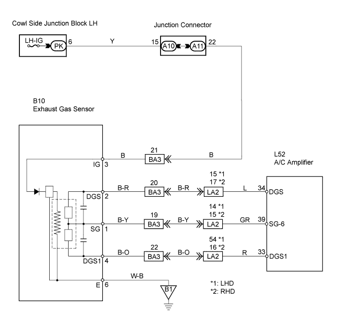
| 3.CHECK WIRE HARNESS (EXHAUST GAS SENSOR - BODY GROUND) |
 |
Disconnect the B10 exhaust gas sensor connector.
Measure the resistance of the wire harness side connector.
| Tester Connection | Condition | Specified Condition |
| B10-6 (E) - Body ground | Always | Below 1 Ω |
|
| ||||
| OK | |
| 4.CHECK WIRE HARNESS (EXHAUST GAS SENSOR - BATTERY) |
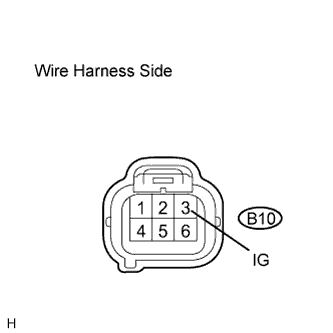 |
Disconnect the B10 exhaust gas sensor connector.
Measure the voltage of the wire harness side connector.
| Tester Connection | Condition | Specified Condition |
| B10-3 (IG) - Body ground | Engine switch on (IG) | 10 to 14 V |
| Engine switch off | Below 1 V |
|
| ||||
| OK | |
| 5.INSPECT EXHAUST GAS SENSOR |
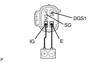 |
Remove the exhaust gas sensor.
After applying battery voltage between terminals 3 (IG) and 6 (E) for more than 120 seconds, measure the resistance between terminals 1 (SG) and 4 (DGS1).
Measure the resistance of the sensor.
| Tester Connection | Condition | Specified Condition |
| 1 (SG) - 4 (DGS1) | 10 to 35°C (50 to 95°F) | 5 to 100 kΩ |
|
| ||||
| OK | |
| 6.CHECK WIRE HARNESS (EXHAUST GAS SENSOR - A/C AMPLIFIER) |
 |
Disconnect the B10 exhaust gas sensor connector.
Disconnect the L52 A/C amplifier connector.
Measure the resistance of the wire harness side connectors.
| Tester Connection | Condition | Specified Condition |
| B10-1 (SG) - L52-39 (SG-6) | Always | Below 1 Ω |
| B10-4 (DGS1) - L52-33 (DGS1) | Always | Below 1 Ω |
| L52-39 - (SG-6) - Body ground | Always | Below 1 Ω |
| L52-33 - (DGS1) - Body ground | Always | 10 kΩ or higher |
|
| ||||
| OK | ||
| ||
