DTC C1252/52 Brake Booster Pump Motor on Time Abnormally Long |
DTC C1253/53 Hydro Booster Pump Motor Relay Malfunction |
| DTC No. | INF Code | DTC Detection Condition | Trouble Area |
| C1252/52 | 130 | Motor relay is on for at least 5 minute. |
|
| C1253/53 | 132 | Motor relay 1 coil is energized for at least 1 second when linear solenoid power source voltage (BS1) is 9.5 V or more and motor relay 1 is off. |
|
| ↑ | 133 | Motor relay 1 coil is not energized for at least 1 second when linear solenoid power source voltage (BS1) is 9.5 V or more and motor relay 1 is on. | ↑ |
| ↑ | 134 | When the linear solenoid power supply 1 (BS1) is 7 V or more, either of DI1 or DI2 voltage is 7 V or more, and the motor relay 1 is on, MTT input of less than 5.3 V continues for 1 second or more. |
|
| ↑ | 136 | Motor relay 2 coil is energized for at least 1 second when linear solenoid power source voltage (BS2) is 9.5 V or more and motor relay 2 is off. |
|
| ↑ | 137 | Motor relay 2 coil is not energized for at least 1 second when linear solenoid power source voltage (BS2) is 9.5 V or more and motor relay 2 is on. | ↑ |
| ↑ | 138 | When the linear solenoid power supply 2 (BS2) is 7 V or more, either of DI1 or DI2 voltage is 7 V or more, and the motor relay 2 is on, MTT input of less than 5.3 V continues for 1 second or more. |
|
| ↑ | 140 | MTT input is 3.5 V or more for at least 2 seconds when motor relay 1 and 2 are off. |
|
| 1.INSPECT FUSE (ABS1, ABS2 AND ABS MOTOR FUSES) |
Remove the ABS1, ABS2 and ABS MOTOR fuses from the engine room R/B (J/B) No.1.
Check the ABS1, ABS2 and ABS MOTOR fuses.
|
| ||||
| OK | |
| 2.PERFORM ACTIVE TEST BY INTELLIGENT TESTER (ECB MOTOR RELAY) |
Connect the intelligent tester to the DLC3.
Turn the engine switch on (IG).
Select the ACTIVE TEST mode on the intelligent tester.
| Item (Display) | Measurement Item / Range (Display) | Normal Condition |
| ECB Motor Relay | Turns ECB motor relay 1 ON / OFF | Operation of relay (clicking sound) and motor can be heard |
| ECB Motor Relay 2 | Turns ECB motor relay 2 ON / OFF | Operation of relay (clicking sound) and motor can be heard |
Check the operation sound of the ECB motor relay and motor when operating it with the intelligent tester.
|
| ||||
| OK | |
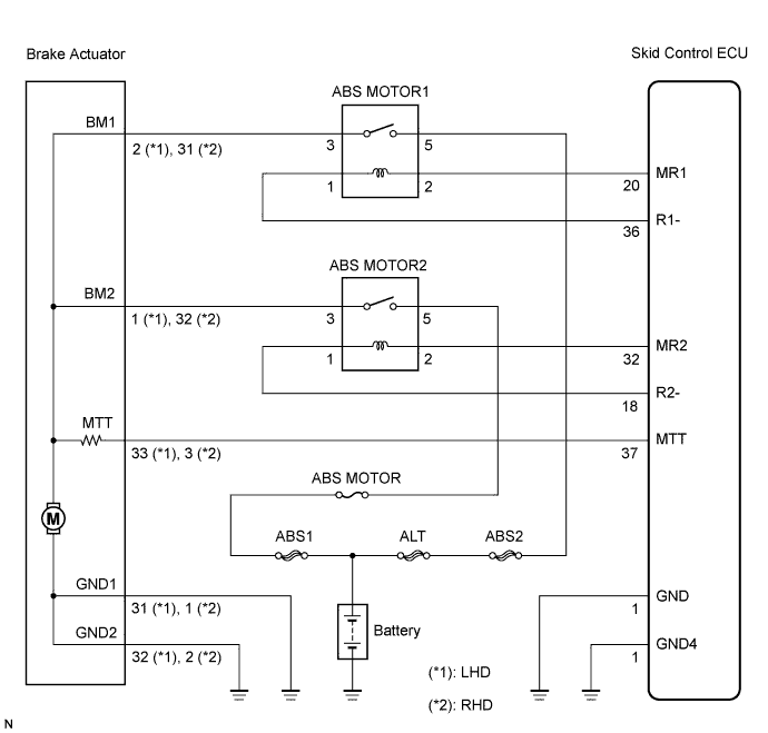
| 3.INSPECT BRAKE ACTUATOR ASSEMBLY |
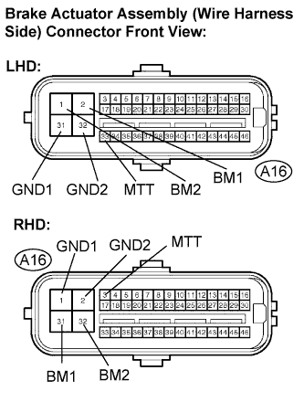 |
Disconnect the brake actuator assembly connector.
Measure the resistance according to the value(s) in the table below.
| Tester Connection | Specified Condition |
| A16-2 (BM1) - A16-31 (GND1) | Below 10 Ω |
| A16-1 (BM2) - A16-31 (GND1) | Below 10 Ω |
| A16-2 (BM1) - A16-1 (BM2) | Below 1 Ω |
| A16-31 (GND1) - A16-32 (GND2) | Below 1 Ω |
| A16-2 (BM1) - A16-33 (MTT) | About 33 Ω |
| A16-1 (BM2) - A16-33 (MTT) | About 33 Ω |
| Tester Connection | Specified Condition |
| A16-31 (BM1) - A16-1 (GND1) | Below 10 Ω |
| A16-32 (BM2) - A16-1 (GND1) | Below 10 Ω |
| A16-31 (BM1) - A16-32 (BM2) | Below 1 Ω |
| A16-1 (GND1) - A16-2 (GND2) | Below 1 Ω |
| A16-31 (BM1) - A16-3 (MTT) | About 33 Ω |
| A16-32 (BM2) - A16-3 (MTT) | About 33 Ω |
|
| ||||
| OK | |
| 4.CHECK HARNESS AND CONNECTOR (SKID CONTROL ECU TO BRAKE ACTUATOR ASSEMBLY) |
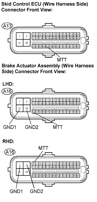 |
Disconnect the skid control ECU connector and brake actuator assembly connector.
Measure the resistance according to the value(s) in the table below.
| Tester Connection | Specified Condition |
| A13-37 (MTT) - A16-33 (MTT) | Below 1 Ω |
| A13-37 (MTT) - Body ground | 10 kΩ or higher |
| A16-31 (GND1) - Body ground | Below 1 Ω |
| A16-32 (GND2) - Body ground | Below 1 Ω |
| Tester Connection | Specified Condition |
| A13-37 (MTT) - A16-3 (MTT) | Below 1 Ω |
| A13-37 (MTT) - Body ground | 10 kΩ or higher |
| A16-1 (GND1) - Body ground | Below 1 Ω |
| A16-2 (GND2) - Body ground | Below 1 Ω |
|
| ||||
| OK | |
| 5.READ VALUE OF INTELLIGENT TESTER (ACCUMULATOR PRESSURE SENSOR) |
Connect the intelligent tester to the DLC3.
Turn the engine switch on (IG).
Select the DATA LIST mode on the intelligent tester.
| Item (Display) | Measurement Item / Range (Display) | Normal Condition |
| Accumulator Sensor | Accumulator pressure sensor / min.: 0 V, max.: 5 V | Specified value: 2.6 to 3.8 V |
Depress the brake pedal 4 or 5 times to operate the pump motor, and check the output value on the intelligent tester with the motor stopped (not braking).
|
| ||||
| OK | |
| 6.INSPECT ABS MOTOR RELAY |
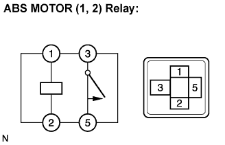 |
Remove the ABS MOTOR1 relay and ABS MOTOR2 relay.
Measure the resistance according to the value(s) in the table below.
| Tester Connection | Condition | Specified Condition |
| 3 - 5 | Always | 10 kΩ or higher (No continuity) |
| 3 - 5 | Apply B+ between terminal 1 and 2 | Below 1 Ω (Continuity) |
|
| ||||
| OK | |
| 7.INSPECT ABS MOTOR RELAY (POWER SOURCE TERMINAL) |
 |
Remove the ABS MOTOR1 relay and ABS MOTOR2 relay.
Measure the voltage according to the value(s) in the table below.
| Tester Connection | Specified Condition |
| 5 - Body ground | 10 to 14 V |
|
| ||||
| OK | |
| 8.CHECK HARNESS AND CONNECTOR (BRAKE ACTUATOR ASSEMBLY TO ENGINE ROOM R/B NO.3) |
 |
Disconnect the brake actuator assembly connector.
Remove the ABS MOTOR1 relay and ABS MOTOR2 relay.
Measure the resistance according to the value(s) in the table below.
| Tester Connection | Specified Condition |
| A16-2 (BM1) - ABS MOTOR1 relay (3) | Below 1 Ω |
| A16-1 (BM2) - ABS MOTOR2 relay (3) | Below 1 Ω |
| Tester Connection | Specified Condition |
| A16-31 (BM1) - ABS MOTOR1 relay (3) | Below 1 Ω |
| A16-32 (BM2) - ABS MOTOR2 relay (3) | Below 1 Ω |
Measure the resistance according to the value(s) in the table below.
| Tester Connection | Specified Condition |
| A16-2 (BM1) - Body ground | 10 kΩ or higher |
| A16-1 (BM2) - Body ground | 10 kΩ or higher |
| Tester Connection | Specified Condition |
| A16-31 (BM1) - Body ground | 10 kΩ or higher |
| A16-32 (BM2) - Body ground | 10 kΩ or higher |
|
| ||||
| OK | |
| 9.CHECK HARNESS AND CONNECTOR (SKID CONTROL ECU TO ENGINE ROOM R/B NO.3) |
 |
Disconnect the skid control ECU (A13, A15) connectors.
Remove the ABS MOTOR1 relay and ABS MOTOR2 relay.
Measure the resistance according to the value(s) in the table below.
| Tester Connection | Specified Condition |
| A13-20 (MR1) - ABS MOTOR1 relay (2) | Below 1 Ω |
| A13-36 (R1-) - ABS MOTOR1 relay (1) | Below 1 Ω |
| A15-18 (R2-) - ABS MOTOR2 relay (1) | Below 1 Ω |
| A15-32 (MR2) - ABS MOTOR2 relay (2) | Below 1 Ω |
Measure the resistance according to the value(s) in the table below.
| Tester Connection | Specified Condition |
| A13-20 (MR1) - Body ground | 10 kΩ or higher |
| A13-36 (R1-) - Body ground | 10 kΩ or higher |
| A15-18 (R2-) - Body ground | 10 kΩ or higher |
| A15-32 (MR2) - Body ground | 10 kΩ or higher |
|
| ||||
| OK | |
| 10.RECONFIRM DTC |
Clear the DTC (Click here).
Turn the engine switch on (IG).
Check if the same DTCs are recorded (Click here).
| Condition | Proceed To |
| DTCs (C1252/52 and C1253/53) are not output | A |
| DTCs (C1252/52 and C1253/53) are output | B |
|
| ||||
| A | ||
| ||
