DTC No.
| INF Code
| DTC Detection Condition
| Trouble Area
|
C1241/41
| 81
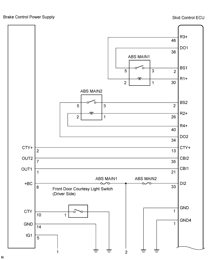
| After starting the engine, any of the following is detected in the main relay 1 line:
- With the main relay 1 and the relay contact ON, the voltage of relay power supply terminal (BS1) is below 8.9 V and the actual current, which is supplied by the relay, does not reach the specified value at any of the linear solenoids for 0.03 seconds or more.
- With the main relay 1 and the relay contact ON, the voltage of relay power supply terminal (BS1) is below 8.9 V and the brake pedal is not depressed for 3 seconds or more.
- When 0.05 seconds elapsed after main relay 1 is turned on and the relay contact is ON, the voltage of relay power supply terminal (BS1) is below 8.9 V and even one wheel is prohibited from braking while depressing the brake pedal.
- While the main relay 1 ON continues, the voltage of relay output terminal (R1+) becomes lower than 8.5 V and the relay contact OFF continues for 0.2 seconds or more.
- With the pressure sensor power supply voltage (VCM) 4.7 V or less or 5.3 V or more, the voltage of relay output terminal (R1+) in the relevant lines is 8.5 V or less for 0.05 seconds or more.
| - Battery
- ABS MAIN1 relay
- ABS MAIN2 relay
- Charging system
- Power source circuit
|
↑
| 82
| After starting the engine, any of the following is detected in the main relay 2 line:
- With the main relay 2 and the relay contact ON, the voltage of relay power supply terminal (BS2) is below 8.9 V and the actual current, which is supplied by the relay, does not reach the specified value at any of the linear solenoids for 0.03 seconds or more.
- With the main relay 2 and the relay contact ON, the voltage of relay power supply terminal (BS2) is below 8.9 V and the brake pedal is not depressed for 3 seconds or more.
- When 0.05 seconds elapsed after main relay 2 is turned on and the relay contact is ON, the voltage of relay power supply terminal (BS2) is below 8.9 V and even one wheel is prohibited from braking while depressing the brake pedal.
- While the main relay 2 ON continues, the voltage of relay output terminal (R2+) becomes lower than 8.5 V and the relay contact OFF continues for 0.2 seconds or more.
- With the pressure sensor power supply voltage (VCM) 4.7 V or less or 5.3 V or more, the voltage of relay output terminal (R2+) in the relevant lines is 8.5 V or less for 0.05 seconds or more.
| ↑
|
↑
| 83
| Capacitor mode signal is received from brake control power supply for 3 seconds or more when starting the engine.
| - Battery
- Charging system
- Brake control power supply
|
↑
| 91
92
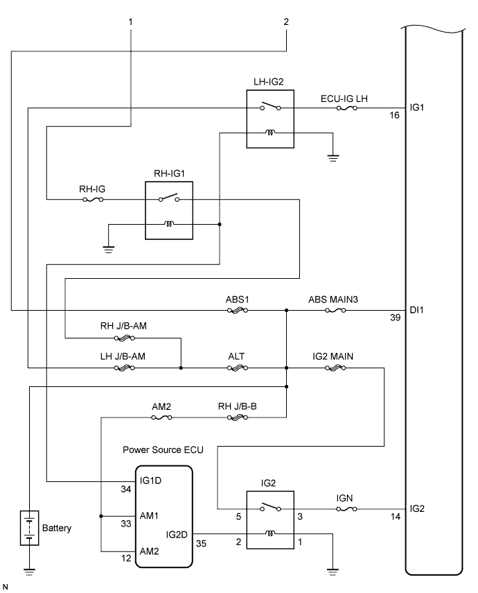
| At a vehicle speed of 3 km/h or more, the IG1 terminal voltage is 9.7 or less or R1+ is less than 8.5 V for 10 seconds or more.
| - Battery
- Charging system
- Power source circuit
|
↑
| 93
94
| With the R1+ terminal voltage 8.5 V or more, malfunction in the wheel speed sensor power supply continues for 60 seconds or more.
| ↑
|
C1242/42
| 87
| The power supply voltage is not applied to the IG1 terminal (below 3.5 V), power supply voltage is applied to the IG2 terminal (3.5 V or more), and DI1 terminal voltage is 9.5 V or more for 4 seconds or more.
| - Power source circuit
- Skid control ECU
|
↑
| 88
| The Power supply voltage is applied to the IG1 terminal (3.5 V or more), power supply voltage is not applied to the IG2 terminal (below 3.5 V), and DI1 terminal voltage is 9.5 V or more for 4 seconds or more.
| ↑
|