THEFT DETERRENT SYSTEM > IG Power Source Circuit |

| 1.CHECK BASIC FUNCTION (ENTRY AND START FUNCTION) |
Check that the basic function of the entry and start system operates normally.
|
| ||||
| OK | |
| 2.INSPECT FUSE (AM2, ECU-IG RH) |
Remove the AM2 and ECU-IG RH fuses from the cowl side junction block.
Measure the resistance of the fuses.
|
| ||||
| OK | |
| 3.CHECK WIRE HARNESS (COWL SIDE JUNCTION BLOCK RH - BATTERY) |
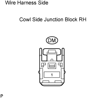 |
Disconnect the DM junction block connector.
Measure the voltage of the wire harness side connector.
| Tester Connection | Specified Condition |
| DM-1 - Body ground | 10 to 14 V |
|
| ||||
| OK | |
| 4.CHECK COWL SIDE JUNCTION BLOCK RH |
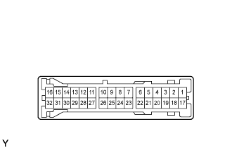 |
Measure the voltage between the terminal of the connector and body ground.
| Tester Connection | Specified Condition |
| DD-4 - Body ground | 10 to 14 V |
|
| ||||
| OK | |
| 5.CHECK WIRE HARNESS (COWL SIDE JUNCTION BLOCK RH - BODY GROUND) |
 |
Disconnect the DD junction block connector.
Measure the resistance of the wire harness side connector.
| Tester Connection | Specified Condition |
| DD-7 - Body ground | Below 1 Ω |
|
| ||||
| OK | |
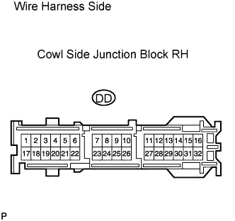
| 6.CHECK WIRE HARNESS (COWL SIDE JUNCTION BLOCK RH - POWER SOURCE CONTROL ECU) |
 |
Disconnect the DD junction block connector.
Disconnect the L73 ECU connector.
Measure the resistance of the wire harness side connectors.
| Tester Connection | Specified Condition |
| DD-4 - L73-33 (AM1) | Below 1 Ω |
| DD-6 - L73-34 (IG1D) | Below 1 Ω |
| DD-4 or L73-33 (AM1) - Body ground | 10 kΩ or higher |
| DD-6 or L73-34 (IG1D) - Body ground | 10 kΩ or higher |
|
| ||||
| OK | ||
| ||
