HOOD LOCK CONTROL CABLE ASSEMBLY > INSTALLATION |
| 1. INSTALL HOOD LOCK CONTROL CABLE ASSEMBLY |
 |
Pass the cable into the engine room.
Pass the cable rear side through the grommet until the cable stopper is attached to the grommet.
Pass the cable front side through the upper radiator support.
Connect the clamps as shown in the illustration.

| 2. INSTALL HOOD LOCK CONTROL LEVER SUB-ASSEMBLY |
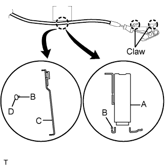 |
| Area | Part Name |
| A | Junction block |
| B | Hood lock control cable |
| C | Parking brake pedal |
| D | Parking brake cable |
Install the hood lock lever and connect the hood lock control cable.
Attach the 2 claws.
| 3. INSTALL HOOD LOCK ASSEMBLY |
 |
Apply MP grease to the sliding areas of the lock.
 |
Install the hood lock.
Install the 2 bolts and nut.
Install a new cap.
Connect the hood lock control cable.
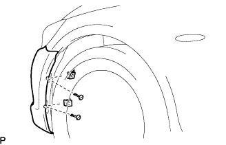
| 4. INSTALL FRONT FENDER PROTECTOR UPPER LH |
 |
Attach the 3 clips to install the protector.
| 5. INSTALL HOOD LOCK CONTROL CABLE COVER |
 |
Attach the claw and install the cable cover.
Install the 3 screws.
| 6. INSTALL MILLIMETER WAVE RADAR SENSOR ASSEMBLY (w/ Cruise Control System) |
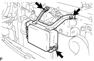 |
Install the sensor with the 3 bolts.
Connect the connector.
| 7. INSTALL FRONT BUMPER COVER |
Connect the ultrasonic sensor connector.
 |
Attach the 3 claws on the LH side.
Attach the 3 claws on the RH side.
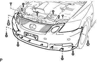 |
Install the bumper cover with the 2 clips, 6 screws and 5 bolts.
| 8. INSTALL FRONT FENDER LINER RH |
| 9. INSTALL FRONT FENDER LINER LH |
 |
Install the fender liner with the 2 clips.
| 10. INSTALL ENGINE UNDER COVER |
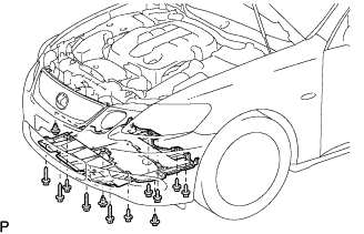 |
Install the under cover with the 3 clips and 10 screws.
| 11. INSTALL COOL AIR INTAKE DUCT SEAL |
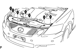 |
Install the duct seal with the 7 clips.
| 12. INSTALL ENGINE ROOM SIDE COVER LH |
 |
Install the side cover with the 3 clips.
| 13. CONNECT CABLE TO NEGATIVE BATTERY TERMINAL |
| 14. PERFORM INITIALIZATION |
Perform initialization (Click here).
