FRONT POWER SEAT CONTROL SYSTEM (w/ Seat Position Memory System) > One or more Power Seat Motors do not Operate |


| 1.CHECK FRONT POWER SEAT OPERATION |
Check that each function of the power seat operates normally by using the front power seat switches.
| Result | Proceed to |
| All front power seat switch operations are malfunctioning except lumbar front power seat switch operation | A |
| Only lumbar front seat switch operation is malfunctioning | B |
|
| ||||
| A | |
| 2.READ VALUE OF INTELLIGENT TESTER (FRONT POWER SEAT SWITCH) |
Check the Data List for proper functioning of the front power seat switch.
| Item | Measurement Item / Display (Range) | Normal Condition | Diagnostic Note |
| Reclining Rear | Reclining switch signal (Rearward) / ON or OFF | ON: Reclining switch (Rearward) is ON OFF: Reclining switch (Rearward) is OFF | - |
| Reclining Front | Reclining switch signal (Forward) / ON or OFF | ON: Reclining switch (Forward) is ON OFF: Reclining switch (Forward) is OFF | - |
| Front Vertical Down | Front vertical switch signal (Downward) / ON or OFF | ON: Front vertical switch (Downward) is ON OFF: Front vertical switch (Downward) is OFF | - |
| Front Vertical Up | Front vertical switch signal (Upward) / ON or OFF | ON: Front vertical switch (Upward) is ON OFF: Front vertical switch (Upward) is OFF | - |
| Lifter Switch Down | Lifter switch signal (Downward) / ON or OFF | ON: Lifter switch (Downward) is ON OFF: Lifter switch (Downward) is OFF | - |
| Lifter Switch Up | Lifter switch signal (Upward) / ON or OFF | ON: Lifter switch (Upward) is ON OFF: Lifter switch (Upward) is OFF | - |
| Slide Rear | Sliding switch signal (Rearward) / ON or OFF | ON: Sliding switch (Rearward) is ON OFF: Sliding switch (Rearward) is OFF | - |
| Slide Front | Sliding switch signal (Forward) / ON or OFF | ON: Sliding switch (Forward) is ON OFF: Sliding switch (Forward) is OFF | - |
|
| ||||
| OK | |
| 3.PERFORM ACTIVE TEST BY INTELLIGENT TESTER (POWER SEAT MOTOR) |
Select the Active Test, use the intelligent tester to generate a control command, and then check that the power seat motors operate.
| Item | Test Details | Diagnostic Note |
| Seat Reclining | Seat reclining operation FRONT / REAR | - |
| Front Vertical Operation | Seat front vertical operation UP / DOWN | - |
| Lifter Operation | Seat lifter operation UP / DOWN | - |
| Seat Slide Operation | Seat sliding operation FRONT / REAR | - |
| Result | Proceed to |
| NG (LH seat) | A |
| NG (RH seat) | B |
| OK | C |
|
| ||||
|
| ||||
| A | |
| 4.INSPECT FRONT SEAT FRAME WITH ADJUSTER LH (SLIDE MOTOR, FRONT VERTICAL MOTOR, LIFTER MOTOR, RECLINING MOTOR) |
    |
Remove the front seat adjuster LH.
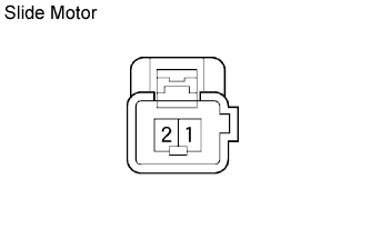
Check operation of the slide motor.
Check if the seat adjuster moves smoothly when the battery is connected to the slide motor connector terminals.
| Measurement Condition | Operation Direction |
| Battery positive (+) → 1 Battery negative (-) → 2 | Forward |
| Battery positive (+) → 2 Battery negative (-) → 1 | Rearward |
Check operation of the front vertical motor.
Check if the seat adjuster moves smoothly when the battery is connected to the front vertical motor connector terminals.
| Measurement Condition | Operation Direction |
| Battery positive (+) → 1 Battery negative (-) → 2 | Upward |
| Battery positive (+) → 2 Battery negative (-) → 1 | Downward |
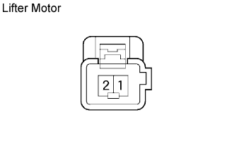
Check operation of the lifter motor.
Check if the seat adjuster moves smoothly when the battery is connected to the lifter motor connector terminals.
| Measurement Condition | Operation Direction |
| Battery positive (+) → 2 Battery negative (-) → 1 | Upward |
| Battery positive (+) → 1 Battery negative (-) → 2 | Downward |
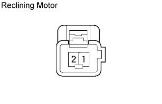
Check operation of the reclining motor.
Check if the seat adjuster moves smoothly when the battery is connected to the reclining motor connector terminals.
| Measurement Condition | Operation Direction |
| Battery positive (+) → 2 Battery negative (-) → 1 | Forward |
| Battery positive (+) → 1 Battery negative (-) → 2 | Rearward |
|
| ||||
| NG | ||
| ||
| 5.INSPECT FRONT SEAT FRAME WITH ADJUSTER RH (SLIDE MOTOR, FRONT VERTICAL MOTOR, LIFTER MOTOR, RECLINING MOTOR) |
|
Remove the front seat adjuster RH.
Check operation of the slide motor.
Check if the seat adjuster moves smoothly when the battery is connected to the slide motor connector terminals.
| Measurement Condition | Operation Direction |
| Battery positive (+) → 2 Battery negative (-) → 1 | Forward |
| Battery positive (+) → 1 Battery negative (-) → 2 | Rearward |
Check operation of the front vertical motor.
Check if the seat adjuster moves smoothly when the battery is connected to the front vertical motor connector terminals.
| Measurement Condition | Operation Direction |
| Battery positive (+) → 2 Battery negative (-) → 1 | Upward |
| Battery positive (+) → 1 Battery negative (-) → 2 | Downward |
Check operation of the lifter motor.
Check if the seat adjuster moves smoothly when the battery is connected to the lifter motor connector terminals.
| Measurement Condition | Operation Direction |
| Battery positive (+) → 1 Battery negative (-) → 2 | Upward |
| Battery positive (+) → 2 Battery negative (-) → 1 | Downward |
Check operation of the reclining motor.
Check if the seat adjuster moves smoothly when the battery is connected to the reclining motor connector terminals.
| Measurement Condition | Operation Direction |
| Battery positive (+) → 2 Battery negative (-) → 1 | Forward |
| Battery positive (+) → 1 Battery negative (-) → 2 | Rearward |
|
| ||||
| OK | |
| 6.CHECK WIRE HARNESS (POSITION CONTROL ECU & SWITCH ASSEMBLY - POWER SEAT MOTOR ASSEMBLY AND BODY GROUND) |
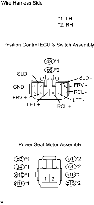 |
Disconnect the d8 or c6 switch connector.
Disconnect the d3, d4, d10, d15, c1, c4, c10 or c15 motor connector.
Measure the resistance of the wire harness side connectors.
| Tester Connection | Specified Condition |
| d8-3 (SLD-) - d3-2 | Below 1 Ω |
| d8-2 (SLD+) - d3-1 | Below 1 Ω |
| d8-4 (FRV-) - d4-2 | Below 1 Ω |
| d8-6 (FRV+) - d4-1 | Below 1 Ω |
| d8-9 (LFT-) - d10-1 | Below 1 Ω |
| d8-7 (LFT+) - d10-2 | Below 1 Ω |
| d8-10 (RCL-) - d15-1 | Below 1 Ω |
| d8-8 (RCL+) - d15-2 | Below 1 Ω |
| d8-1 (GND) - Body ground | Below 1 Ω |
| Tester Connection | Specified Condition |
| c6-3 (SLD-) - c1-1 | Below 1 Ω |
| c6-2 (SLD+) - c1-2 | Below 1 Ω |
| c6-4 (FRV-) - c4-1 | Below 1 Ω |
| c6-6 (FRV+) - c4-2 | Below 1 Ω |
| c6-9 (LFT-) - c10-2 | Below 1 Ω |
| c6-7 (LFT+) - c10-1 | Below 1 Ω |
| c6-10 (RCL-) - c15-1 | Below 1 Ω |
| c6-8 (RCL+) - c15-1 | Below 1 Ω |
| c6-1 (GND) - Body ground | Below 1 Ω |
|
| ||||
| OK | ||
| ||
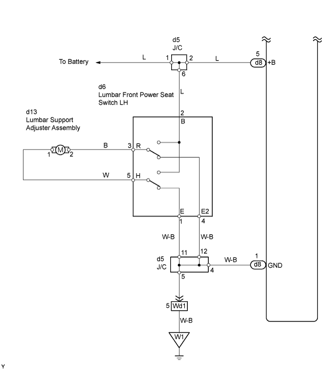
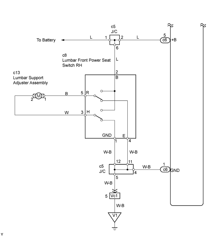
| 7.CHECK WIRE HARNESS (LUMBAR FRONT POWER SEAT SWITCH - LUMBAR FRONT POWER SEAT SWITCH AND BODY GROUND) |
 |
Disconnect the d6 or c8 switch connector.
Measure the voltage and resistance of the wire harness side connectors.
| Tester Connection | Specified Condition |
| d6-2 (B) - Body ground | 10 to 14 V |
| Tester Connection | Specified Condition |
| c8-2 (B) - Body ground | 10 to 14 V |
| Tester Connection | Specified Condition |
| d6-1 (E) - Body ground | Below 1 Ω |
| d6-4 (E2) - Body ground | Below 1 Ω |
| Tester Connection | Specified Condition |
| c8-1 (GND) - Body ground | Below 1 Ω |
| c8-4 (E) - Body ground | Below 1 Ω |
|
| ||||
| OK | |
| 8.INSPECT LUMBAR FRONT POWER SEAT SWITCH |
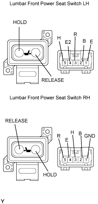 |
Remove the switch.
Measure the resistance between the terminals when the switch is operated.
| Tester Connection | Switch Condition | Specified Condition |
| 2 (B) - 3 (R) | HOLD | Below 1 Ω |
| 4 (E2) - 5 (H) | HOLD | Below 1 Ω |
| 1 (E) - 3 (R) | OFF | Below 1 Ω |
| 5 (H) - 4 (E2) | OFF | Below 1 Ω |
| 1 (E) - 3 (R) | RELEASE | Below 1 Ω |
| 2 (B) - 5 (H) | RELEASE | Below 1 Ω |
| Tester Connection | Switch Condition | Specified Condition |
| 1 (GND) - 5 (R) | HOLD | Below 1 Ω |
| 2 (B) - 3 (H) | HOLD | Below 1 Ω |
| 1 (GND) - 5 (R) | OFF | Below 1 Ω |
| 3 (H) - 4 (E) | OFF | Below 1 Ω |
| 2 (B) - 5 (R) | RELEASE | Below 1 Ω |
| 3 (H) - 4 (E) | RELEASE | Below 1 Ω |
|
| ||||
| OK | |
| 9.INSPECT LUMBAR SUPPORT ADJUSTER ASSEMBLY |
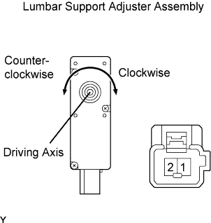 |
Remove the lumbar support adjuster.
Check operation of the lumbar support adjuster.
Check that the lumbar support adjuster moves smoothly when the battery is connected to the lumbar support adjuster motor connector terminals.
| Measurement Condition | Operation Direction |
| Battery positive (+) → 1 Battery negative (-) → 2 | Clockwise |
| Battery positive (+) → 2 Battery negative (-) → 1 | Counterclockwise |
|
| ||||
| OK | ||
| ||
