DTC P0340 Camshaft Position Sensor Circuit Malfunction |
DTC P0341 Camshaft Position Sensor "A" Circuit Range / Performance (Bank 1 or Single Sensor) |
DTC P0345 Camshaft Position Sensor "A" Circuit (Bank 2) |
DTC P0346 Camshaft Position Sensor "A" Circuit Range / Performance (Bank 2) |
| DTC No. | DTC Detection Condition | Trouble Area |
| P0340 P0345 |
|
|
| P0341 P0346 | When crankshaft rotates twice, VVT sensor signal is input to ECM 12 times or more (1 trip detection logic) | Same as DTC No. P0340/P0345 |

| Tester Connection | Specified Condition |
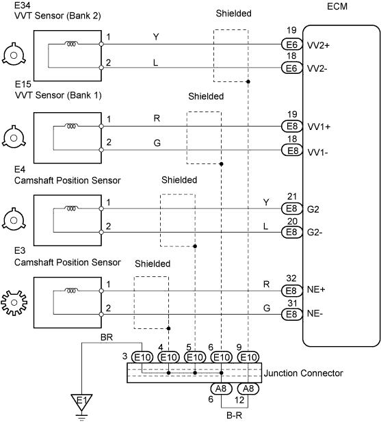
| VV1+ (E8-19) - VV1- (E8-18) | Correct waveform is as shown |
| VV2+ (E6-19) - VV2- (E6-18) | Correct waveform is as shown |
| NE+ (E8-32) - NE- (E8-31) | Correct waveform is as shown |
| 1.INSPECT VVT SENSOR (RESISTANCE) |
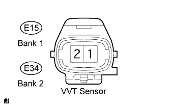 |
Disconnect the E15 and E34 VVT sensor connectors.
Measure the resistance of the VVT sensor.
| Tester Connection | Condition | Specified Condition |
| 1 - 2 | Cold | 835 to 1,400 Ω |
| 1 - 2 | Hot | 1,060 to 1,645 Ω |
|
| ||||
| OK | |
| 2.CHECK WIRE HARNESS (VVT SENSOR - ECM) |
 |
Disconnect the E15 and E34 VVT sensor connectors.
Disconnect the E6 and E8 ECM connectors.
Measure the resistance of the wire harness side connectors.
| Tester Connection | Specified Condition |
| E15-1 - E8-19 (VV1+) | Below 1 Ω |
| E15-2 - E8-18 (VV1-) | Below 1 Ω |
| E34-1 - E6-19 (VV2+) | Below 1 Ω |
| E34-2 - E6-18 (VV2-) | Below 1 Ω |
| E15-1 or E8-19 (VV1+) - Body ground | 10 kΩ or higher |
| E15-2 or E8-18 (VV1-) - Body ground | 10 kΩ or higher |
| E34-1 or E6-19 (VV2+) - Body ground | 10 kΩ or higher |
| E34-2 or E6-18 (VV2-) - Body ground | 10 kΩ or higher |
|
| ||||
| OK | |
| 3.CHECK SENSOR INSTALLATION (VVT SENSOR) |
 |
Check the sensor installation.
|
| ||||
| OK | |
| 4.CHECK CRANKSHAFT TIMING PULLEY |
Check the teeth of the crankshaft timing pulley.
|
| ||||
| OK | ||
| ||
