DTC C1249/49 Open in Stop Light Switch Circuit |
| DTC No. | INF Code | DTC Detection Condition | Trouble Area |
| C1249/49 | 520 | Stop light switch circuit is open for at least 10 seconds when IG1 terminal voltage is 9.5 V or more. |
|
| 1.INSPECT FUSE (STOP SW FUSE) |
Remove the STOP SW fuse from the cowl side J/B RH.
Check the STOP SW fuse.
|
| ||||
| OK | |
| 2.READ VALUE OF INTELLIGENT TESTER (STOP LIGHT SWITCH) |
Connect the intelligent tester to the DLC3.
Start the engine.
Select the DATA LIST mode on the intelligent tester.
| Item (Display) | Measurement Item / Range (Display) | Normal Condition |
| Stop Lamp SW | Stop light switch / ON or OFF | ON: Brake pedal depressed OFF: Brake pedal released |
Check that the stop light observed on the intelligent tester changes when the brake pedal is depressed.
|
| ||||
| OK | |
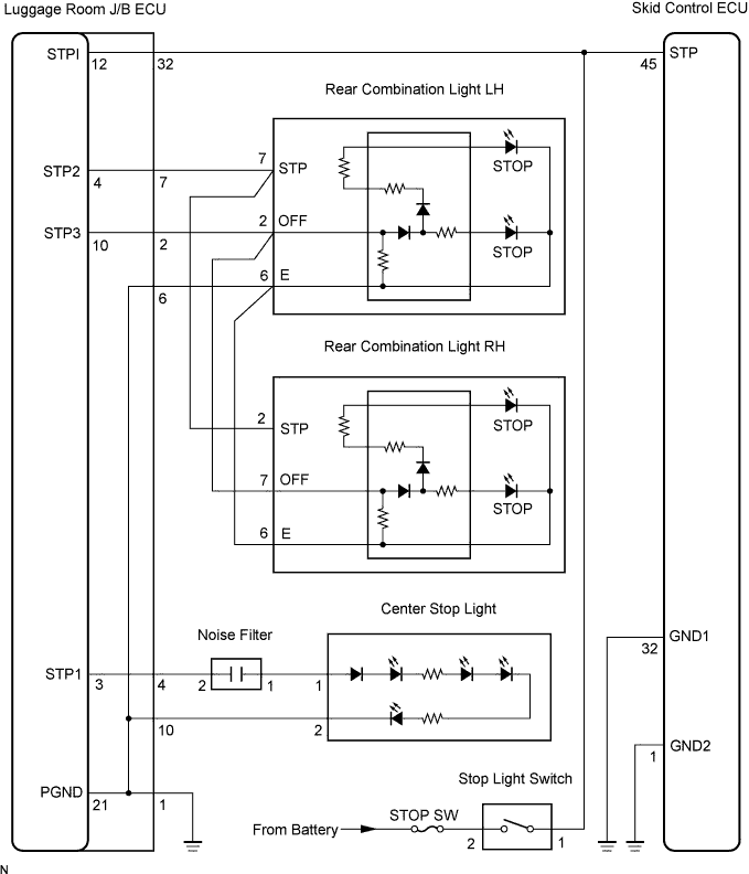
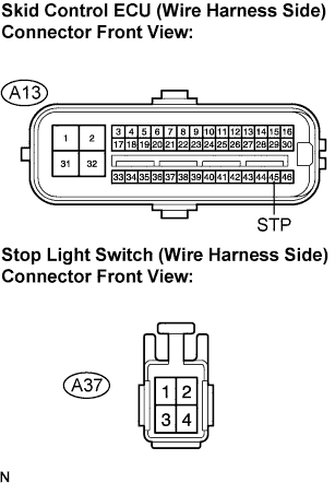
| 3.CHECK HARNESS AND CONNECTOR (SKID CONTROL ECU TO STOP LIGHT SWITCH) |
 |
Disconnect the skid control ECU connector and stop light switch connector.
Measure the resistance according to the value(s) in the table below.
| Tester Connection | Specified Condition |
| A13-45 (STP) - A37-1 | Below 1 Ω |
Measure the resistance according to the value(s) in the table below.
| Tester Connection | Specified Condition |
| A13-45 (STP) - Body ground | 10 kΩ or higher |
|
| ||||
| OK | |
| 4.INSPECT STOP LIGHT SWITCH (POWER SOURCE TERMINAL) |
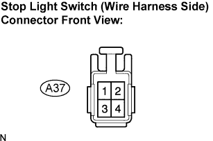 |
Disconnect the stop light switch connector.
Measure the voltage according to the value(s) in the table below.
| Tester Connection | Specified Condition |
| A37-2 - Body ground | 10 to 14 V |
|
| ||||
| OK | |
| 5.INSPECT STOP LIGHT SWITCH |
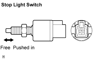 |
Disconnect the stop light switch connector.
Measure the resistance according to the value(s) in the table below.
| Tester Connection | Condition | Specified Condition |
| 1 - 2 | Switch pin free | Below 1 Ω |
| 1 - 2 | Switch pin pushed in | 10 kΩ or higher |
|
| ||||
| OK | |
| 6.INSPECT SKID CONTROL ECU (GND TERMINAL) |
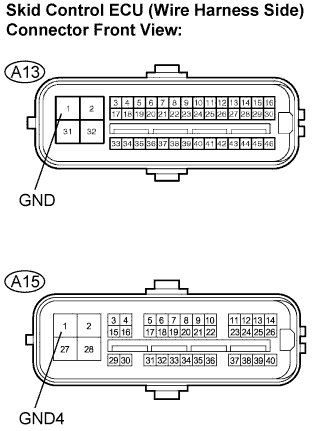 |
Disconnect the skid control ECU (A13, A15) connectors.
Measure the resistance according to the value(s) in the table below.
| Tester Connection | Specified Condition |
| A13-1 (GND) - Body ground | Below 1 Ω |
| A15-1 (GND4) - Body ground | Below 1 Ω |
|
| ||||
| OK | |
| 7.RECONFIRM DTC |
Clear the DTC (Click here).
Start the engine.
Depress the brake pedal several times to test the stop light circuit.
Check if the same DTC is recorded (Click here).
| Condition | Proceed To |
| DTC (C1249/49) is not output | A |
| DTC (C1249/49) is output | B |
|
| ||||
| A | ||
| ||
| 8.CHECK HARNESS AND CONNECTOR (SKID CONTROL ECU TO LUGGAGE ROOM J/B ECU) |
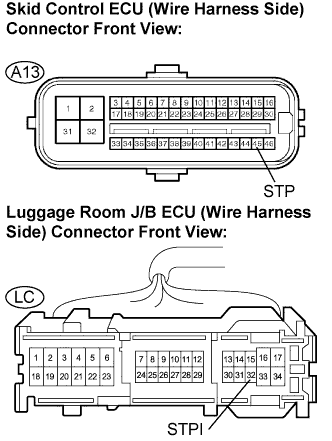 |
Disconnect the skid control ECU connector and luggage room J/B ECU connector.
Measure the resistance according to the value(s) in the table below.
| Tester Connection | Specified Condition |
| A13-45 (STP) - LC-32 (STPI) | Below 1 Ω |
| A13-45 (STP) - Body ground | 10 kΩ or higher |
|
| ||||
| OK | ||
| ||
