ELECTRONICALLY CONTROLLED BRAKE SYSTEM > Slip Indicator Light Remains ON |

| 1.INSPECT CAN COMMUNICATION SYSTEM |
Check if the CAN communication system DTC is output (Click here).
| Condition | Proceed To |
| DTC is not output | A |
| DTC is output | B |
|
| ||||
| A | |
| 2.INSPECT MULTIPLEX COMMUNICATION SYSTEM |
Check if the multiplex communication system DTC is output (Click here).
| Condition | Proceed To |
| DTC is not output | A |
| DTC is output | B |
|
| ||||
| A | |
| 3.INSPECT IF SKID CONTROL ECU CONNECTOR IS SECURELY CONNECTED |
Check the skid control ECU connector's connection.
|
| ||||
| OK | |
| 4.INSPECT BATTERY |
Check the battery voltage.
|
| ||||
| OK | |
| 5.INSPECT TRACTION OFF SWITCH |
 |
Remove the traction OFF switch.
Disconnect the traction control switch connector.
Measure the resistance according to the value(s) in the table below.
| Tester Connection | Condition | Specified Condition |
| 3 - 4 | Pressed | Below 1 Ω |
| 3 - 4 | Not pressed | 10 kΩ or higher |
|
| ||||
| OK | |
| 6.INSPECT TRACTION OFF SWITCH (GROUND TERMINAL) |
 |
Disconnect the traction OFF switch connector.
Measure the resistance according to the value(s) in the table below.
| Tester connection | Specified condition |
| L43-4 - Body ground | Below 1 Ω |
|
| ||||
| OK | |
| 7.CHECK HARNESS AND CONNECTOR (SKID CONTROL ECU TO TRACTION OFF SWITCH) |
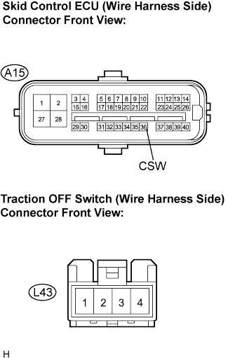 |
Disconnect the skid control ECU connector and the traction OFF switch connector.
Measure the resistance according to the value(s) in the table below.
| Tester connection | Specified condition |
| A15-36 (CSW) - L43-3 | Below 1 Ω |
| A15-36 (CSW) - Body ground | 10 kΩ or higher |
|
| ||||
| OK | |
| 8.INSPECT COMBINATION METER ASSEMBLY |
Check the combination meter assembly (Click here).
|
| ||||
| OK | ||
| ||
