COOLING FAN ECU > ON-VEHICLE INSPECTION |
| 1. CHECK COOLING FAN ECU |
 |
Inspect the input voltage.
Disconnect the cooling fan ECU connector.
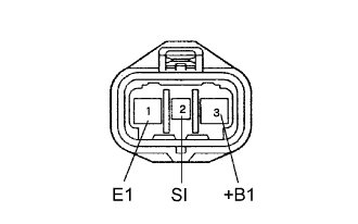
Turn the engine switch on (IG). Check the voltage of the 3 (+B1) terminal of the wire harness side.
Inspect the cooling fan motor (Click here).
Check the resistance of the wire harness side between the ECM (RFC) and cooling fan ECU (SI).
Inspect the ECM power source circuit and ground circuit.
Inspect the input signal and output current.
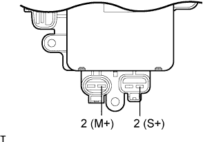 |
Connect the 400 A probe of the ammeter to terminals 2 (M+) and 2 (S+) of the cooling fan motor.
Set the intelligent tester to the oscilloscope.
Using the intelligent tester, check the waveform between terminals A6-10 (RFC) and E7-7 (E1) of the ECM.

| Condition | Input Signal | Output Current |
| Engine stopped (Engine switch on (IG)) | Waveform 1 (Duty ratio 0 %) | (Fan stops) |
| Engine idling (A/C OFF) | Waveform 1 (0 %) | (Fan stops) |
| Engine idling (A/C ON) | Waveform 2 (50 to 70 %) | 2 to 11 A (Fan operates) |
| Engine idling (Coolant temperature sensor connector disconnected) | Waveform 3 (60 to 70 %) | 2 to 11 A (Fan operates) |
