VEHICLE STABILITY CONTROL SYSTEM > Brake Warning Light Remains ON |

| 1.CHECK DTC |
Check if the ABS and/or VSC DTC is output (Click here).
| Condition | Proceed To |
| DTC is not output | A |
| DTC is output | B (Click here) |
|
| ||||
| A | |
| 2.INSPECT CAN COMMUNICATION SYSTEM |
Check if the CAN communication system DTC is output (Click here).
| Condition | Proceed To |
| DTC is not output | A |
| DTC is output | B |
|
| ||||
| A | |
| 3.INSPECT MULTIPLEX COMMUNICATION SYSTEM |
Check if the multiplex communication system DTC is output (Click here).
| Condition | Proceed To |
| DTC is not output | A |
| DTC is output | B |
|
| ||||
| A | |
| 4.INSPECT IF SKID CONTROL ECU CONNECTOR IS SECURELY CONNECTED |
Check if the skid control ECU connector is securely connected.
|
| ||||
| OK | |
| 5.INSPECT BATTERY |
Check the battery voltage.
|
| ||||
| OK | |
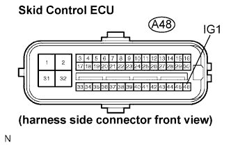
| 6.INSPECT SKID CONTROL ECU (IG1 TERMINAL) |
 |
Disconnect the skid control ECU connector.
Turn the engine switch on (IG).
Measure the voltage according to the value(s) in the table below.
| Tester Connection | Condition | Specified Condition |
| A48-46 (IG1) - Body ground | Engine switch on (IG) | 10 to 14 V |
|
| ||||
| OK | |
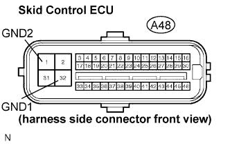
| 7.INSPECT SKID CONTROL ECU (GND TERMINAL) |
 |
Disconnect the skid control ECU connector.
Measure the resistance according to the value(s) in the table below.
| Tester Connection | Specified Condition |
| A48-1 (GND2) - Body ground | Below 1 Ω |
| A48-32 (GND1) - Body ground | Below 1 Ω |
|
| ||||
| OK | |
| 8.INSPECT PARKING BRAKE SWITCH |
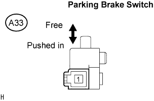 |
Disconnect the parking brake switch connector.
Measure the resistance according to the value(s) in the table below.
| Tester Connection | Condition | Specified Condition |
| A33-1 - Body ground | Parking brake switch ON (Switch pin free) | Below 1 Ω |
| A33-1 - Body ground | Parking brake switch OFF (Switch pin pushed in) | 10 kΩ or higher |
|
| ||||
| OK | |
| 9.CHECK HARNESS AND CONNECTOR (SKID CONTROL ECU TO PARKING BRAKE SWITCH) |
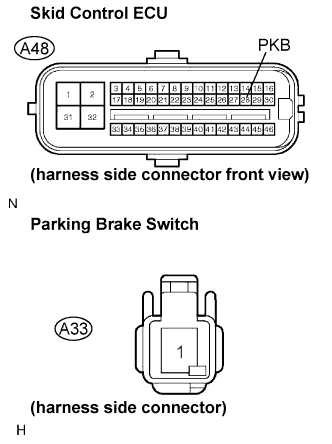 |
Disconnect the skid control ECU connector and parking brake switch.
Measure the resistance according to the value(s) in the table below.
| Tester Connection | Specified Condition |
| A48-28 (PKB) - A33-1 | Below 1 Ω |
| A48-28 (PKB) - Body ground | 10 kΩ or higher |
|
| ||||
| OK | |
| 10.INSPECT BRAKE FLUID LEVEL WARNING SWITCH |
 |
Remove the reservoir tank cap and strainer.
Disconnect the brake fluid level warning switch connector.
Measure the resistance according to the value(s) in the table below.
| Tester Connection | Condition | Specified Condition |
| A23-1 - A23-2 | Float up (Switch OFF) | 1.9 to 2.1 kΩ |
| A23-1 - A23-2 | Float down (Switch ON) | Below 1 Ω |
|
| ||||
| OK | |
| 11.INSPECT HARNESS AND CONNECTOR (BRAKE FLUID LEVEL WARNING SWITCH TO COMBINATION METER) |
 |
Disconnect the combination meter connector.
Measure the resistance according to the value(s) in the table below.
| Tester Connection | Specified Condition |
| L31-28 - A23-1 | Below 1 Ω |
| L31-28 - Body ground | 10 kΩ or higher |
| A23-2 - Body ground | Below 1 Ω |
|
| ||||
| OK | |
| 12.INSPECT COMBINATION METER ASSEMBLY |
Check the combination meter assembly (Click here).
|
| ||||
| OK | ||
| ||
