POWER MIRROR CONTROL SYSTEM > Power Mirror Surface Position is not Memorized |


| 1.CHECK SEAT MEMORY SWITCH FUNCTION (SEAT POSITION MEMORY FUNCTION) |
Check that the driver side seat can be moved using the seat memory switch.
|
| ||||
| OK | |
| 2.CHECK SEAT MEMORY SWITCH FUNCTION (REGISTRATION OF SEAT MEMORY SWITCH) |
Check that the memory operation is properly completed.
|
| ||||
| OK | |
| 3.READ VALUE OF INTELLIGENT TESTER (MIRROR POSITION SENSOR) |
Check the Data List for proper functioning of the mirror position sensor.
| Item | Measurement Item / Range (Display) | Normal Condition | Diagnostic Note |
| Mirror Position Sensor V | Vertical mirror position / Min.: 0, Max.: 5 V | Within 0 to 5 V | - |
| Mirror Position Sensor H | Horizontal mirror position / Min.: 0, Max.: 5 V | Within 0 to 5 V | - |
|
| ||||
| NG | |
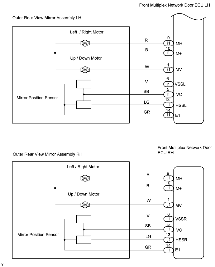
| 4.INSPECT OUTER REAR VIEW MIRROR ASSEMBLY (MIRROR POSITION SENSOR) |
Disconnect the i1 or j1 mirror connector.
Apply battery and dry cell battery voltage to the terminals as shown in the table below.
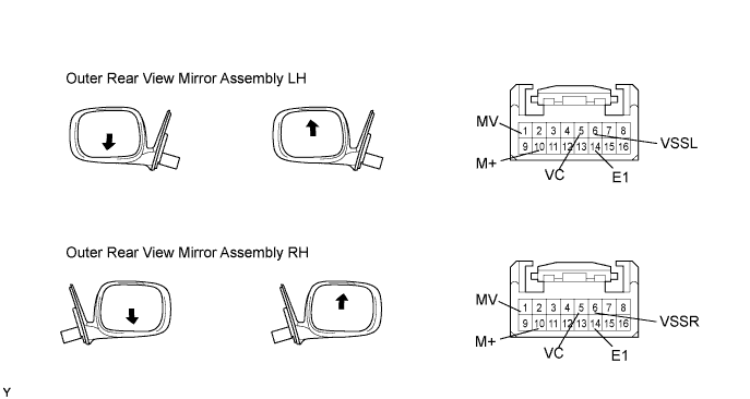
Measure the voltage while the mirror moves between the fully downward and fully upward positions.
| Measurement Connection (Battery) | Measurement Connection (Dry Cell Battery) | Voltmeter Condition | Mirror Condition | Specified Condition |
| Battery positive (+) → Terminal 10 (M+) Battery negative (-) → Terminal 1 (MV) | Battery positive (+) → Terminal 5 (VC) Battery negative (-) → Terminal 14 (E1) | Positive (+) lead → Terminal 6 (VSSL) Negative (-) lead → Terminal 14 (E1) | Turns fully downward | 0 to 1.0 V |
| Battery positive (+) → Terminal 1 (MV) Battery negative (-) → Terminal 10 (M+) | Battery positive (+) → Terminal 5 (VC) Battery negative (-) → Terminal 14 (E1) | Positive (+) lead → Terminal 6 (VSSL) Negative (-) lead → Terminal 14 (E1) | Turns fully upward | 2.8 to 5.0 V |
| Measurement Connection (Battery) | Measurement Connection (Dry Cell Battery) | Voltmeter Condition | Mirror Condition | Specified Condition |
| Battery positive (+) → Terminal 10 (M+) Battery negative (-) → Terminal 1 (MV) | Battery positive (+) → Terminal 5 (VC) Battery negative (-) → Terminal 14 (E1) | Positive (+) lead → Terminal 6 (VSSR) Negative (-) lead → Terminal 14 (E1) | Turns fully downward | 0 to 1.0 V |
| Battery positive (+) → Terminal 1 (MV) Battery negative (-) → Terminal 10 (M+) | Battery positive (+) → Terminal 5 (VC) Battery negative (-) → Terminal 14 (E1) | Positive (+) lead → Terminal 6 (VSSR) Negative (-) lead → Terminal 14 (E1) | Turns fully upward | 2.8 to 5.0 V |
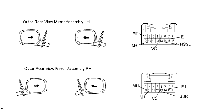
Measure the voltage while the mirror moves between the fully left and fully right positions.
| Measurement Connection (Battery) | Measurement Connection (Dry Cell Battery) | Voltmeter Condition | Mirror Condition | Specified Condition |
| Battery positive (+) → Terminal 9 (MH) Battery negative (-) → Terminal 10 (+M) | Battery positive (+) → Terminal 5 (VC) Battery negative (-) → Terminal 14 (E1) | Positive (+) lead → Terminal 13 (HSSL) Negative (-) lead → Terminal 14 (E1) | Turns to left fully | 2.8 to 5.0 V |
| Battery positive (+) → Terminal 10 (M+) Battery negative (-) → Terminal 9 (MH) | Battery positive (+) → Terminal 5 (VC) Battery negative (-) → Terminal 14 (E1) | Positive (+) lead → Terminal 13 (HSSL) Negative (-) lead → Terminal 14 (E1) | Turns to right fully | 0 to 1.0 V |
| Measurement Connection (Battery) | Measurement Connection (Dry Cell Battery) | Voltmeter Condition | Mirror Condition | Specified Condition |
| Battery positive (+) → Terminal 9 (MH) Battery negative (-) → Terminal 10 (M+) | Battery positive (+) → Terminal 5 (VC) Battery negative (-) → Terminal 14 (E1) | Positive (+) lead → Terminal 13 (HSSR) Negative (-) lead → Terminal 14 (E1) | Turns to left fully | 0 to 1.0 V |
| Battery positive (+) → Terminal 10 (M+) Battery negative (-) → Terminal 9 (MH) | Battery positive (+) → Terminal 5 (VC) Battery negative (-) → Terminal 14 (E1) | Positive (+) lead → Terminal 13 (HSSR) Negative (-) lead → Terminal 14 (E1) | Turns to right fully | 2.8 to 5.0 V |
| Result | Proceed to |
| Outer rear view mirror LH operates normally | A |
| Outer rear view mirror RH operates normally | B |
| Outer rear view mirror LH does not operate normally | C |
| Outer rear view mirror RH does not operate normally | D |
|
| ||||
|
| ||||
|
| ||||
| A | ||
| ||
