DTC B2788 IG2 Signal Malfunction |
| DTC No. | DTC Detecting Condition | Trouble Area |
| B2788 |
|
|

| 1.INSPECT IG2 RELAY |
 |
Remove the IG2 relay from the engine room J/B and R/B No.2.
Measure the resistance according to the value(s) in the table below.
| Tester Connection | Specified Condition |
| 3 - 5 | 10 kΩ or higher |
| 3 - 5 | Below 1 Ω (when battery voltage is applied to terminals 1 and 2) |
|
| ||||
| OK | |
| 2.CHECK HARNESS AND CONNECTOR (STEERING LOCK ACTUATOR ASSEMBLY - BODY GROUND) |
 |
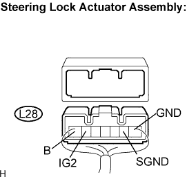
Disconnect the L28 connector from the steering lock actuator assembly.
Measure the resistance according to the value(s) in the table below.
| Tester connection (Symbols) | Condition | Specified condition |
| L28-1 (GND) - Body ground | Always | Below 1 Ω |
| L28-2 (SGND) - Body ground | Always | Below 1 Ω |
|
| ||||
| OK | |
| 3.CHECK HARNESS AND CONNECTOR (STEERING LOCK ACTUATOR ASSEMBLY - BATTERY) |
 |
Measure the voltage according to the value(s) in the table below.
| Tester connection (Symbols) | Condition | Specified condition |
| L28-6 (IG2) - L28-1 (GND) | Engine switch on (IG) | 10 to 14 V |
| L28-6 (IG2) - L28-2 (SGND) | Engine switch on (IG) | 10 to 14 V |
Measure the resistance according to the value(s) in the table below.
| Tester connection (Symbols) | Condition | Specified condition |
| *L28-6 (IG2) - L28-7 (B) | Engine switch off | 10 kΩ higher |
|
| ||||
| NG | ||
| ||
