DTC C1511 Torque Sensor Circuit Malfunction |
DTC C1512 Torque Sensor Circuit Malfunction |
DTC C1513 Torque Sensor Circuit Malfunction |
| DTC No. | Detection Item | Trouble Area |
| C1511 | Torque sensor (TRQ1) signal error or stop |
|
| C1512 | Torque sensor (TRQ2) signal error or stop |
|
| C1513 | Deviation between torque sensors TRQ1 and TRQ2 is out of specification |
|

| 1.CHECK HARNESS AND CONNECTOR (POWER STEERING ECU ASSEMBLY - TORQUE SENSOR) |
 |
Disconnect the C4 connector from the power steering ECU assembly.
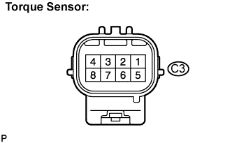
Disconnect the C3 connector from the torque sensor.
Measure the resistance according to the value(s) in the table below.
| Tester connection (Symbols) | Condition | Specified condition |
| C3-1 (INCS) - C4-8 (INCS) | Always | Below 1 Ω |
| C3-2 (INSN) - C4-7 (INSN) | Always | Below 1 Ω |
| C3-4 (TRQV) - C4-1 (TRQV) | Always | Below 1 Ω |
| C3-5 (OUCS) - C4-10 (OUCS) | Always | Below 1 Ω |
| C3-6 (OUSN) - C4-9 (OUSN) | Always | Below 1 Ω |
| C3-7 (TQG2) - C4-14 (TQG2) | Always | Below 1 Ω |
| C3-8 (TQG1) - C4-12 (TQG1) | Always | Below 1 Ω |
| C3-1 (INCS) - Body ground | Always | 10 kΩ or higher |
| C3-2 (INSN) - Body ground | Always | 10 kΩ or higher |
| C3-4 (TRQV) - Body ground | Always | 10 kΩ or higher |
| C3-5 (OUCS) - Body ground | Always | 10 kΩ or higher |
| C3-6 (OUSN) - Body ground | Always | 10 kΩ or higher |
| C3-7 (TQG2) - Body ground | Always | 10 kΩ or higher |
| C3-8 (TQG1) - Body ground | Always | 10 kΩ or higher |
|
| ||||
| OK | |
| 2.INSPECT POWER STEERING LINK ASSEMBLY (TORQUE SENSOR) |
 |
Measure the resistance according to the value(s) in the table below.
| Tester connection (Symbols) | Condition | Specified condition |
| C3-1 (INCS) - C3-7 (TQG2) | Always | 90 to 170 Ω |
| C3-2 (INSN) - C3-7 (TQG2) | Always | 300 to 430 Ω |
| C3-4 (TRQV) - C3-8 (TQG1) | Always | 4 to 14 Ω |
| C3-5 (OUCS) - C3-7 (TQG2) | Always | 90 to 170 Ω |
| C3-6 (OUSN) - C3-7 (TQG2) | Always | 300 to 430 Ω |
|
| ||||
| OK | |
| 3.REPLACE POWER STEERING ECU ASSEMBLY |
Replace the power steering ECU assembly (Click here).
| NEXT | |
| 4.INITIALIZE ROTATION ANGLE SENSOR AND CALIBRATE TORQUE SENSOR ZERO POINT |
Initialize the rotation angle sensor and calibrate the torque sensor zero point (Click here).
| NEXT | |
| 5.RECONFIRM DTC |
Check for DTCs (Click here).
Is DTC C1511, C1512 or C1513 output?
|
| ||||
| OK | ||
| ||
