DTC C1552 PIG Power Supply Voltage Malfunction |
DTC C1554 Power Supply Relay Failure |
| DTC No. | DTC Detection Condition | Trouble Area |
| C1552 | This DTC is detected when power source voltage drops or remains high. |
|
| C1554 | This DTC is detected when the power source relay is stuck, or when an open circuit occurs in the power source relay. |
|
| 1.INSPECT FUSES (ECU-B, EPS FUSE) |
Check for continuity of the ECU-B and EPS fuses.
|
| ||||
| OK | |
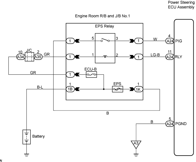
| 2.INSPECT ELECTRIC POWER STEERING RELAY |
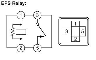 |
Remove the EPS relay from the engine room R/B No.1.
Measure the resistance according to the value(s) in the table below.
| Tester connection | Specified condition |
| 3 - 5 | 10 kΩ or higher |
| 3 - 5 | Below 1 Ω (When battery voltage is applied to terminals 1 and 2) |
|
| ||||
| OK | |
| 3.CHECK HARNESS AND CONNECTOR (EPS RELAY - BATTERY) |
 |
Measure the voltage according to the value(s) in the table below.
| Tester connection | Condition | Specified condition |
| 1 - Body ground | Always | 10 to 14 V |
| 5 - Body ground | Always | 10 to 14 V |
|
| ||||
| OK | |
| 4.CHECK HARNESS AND CONNECTOR (EPS RELAY - POWER STEERING ECU ASSEMBLY) |
 |
Disconnect the A24 connector from the power steering ECU assembly.
Measure the resistance according to the value(s) in the table below.
| Tester connection | Condition | Specified condition |
| A24-4 (PIG) - 3 | Always | Below 1 Ω |
| A24-11 (RLY) - 2 | Always | Below 1 Ω |
| A24-4 (PIG) - Body ground | Always | 10 kΩ or higher |
| A24-11 (RLY) - Body ground | Always | 10 kΩ or higher |
| A24-4 (PIG) - A24-11 (RLY) | Always | 1 MΩ or higher |
|
| ||||
| OK | ||
| ||
