DTC No.
| DTC Detection Item
| Trouble Area
|
C1521
| Motor overcurrent
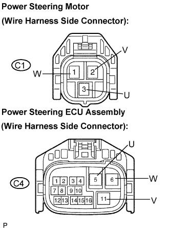
| - Wire harness or connector
- Power steering motor (built into power steering link assembly)
- Power steering ECU assembly
|
C1522
| Motor current sensor malfunction
| - Wire harness or connector
- Power steering motor (built into power steering link assembly)
- Power steering ECU assembly
|
C1523
| Excessively large current deviation
| - Wire harness or connector
- Power steering motor (built into power steering link assembly)
- Power steering ECU assembly
|
C1524
| Voltage error between motor terminals
| - Wire harness or connector
- Power steering motor (built into power steering link assembly)
- Power steering ECU assembly
|