DTC B1000/31 Center Airbag Sensor Assembly Malfunction |
| DTC No. | DTC Detecting Condition | Trouble Area |
| B1000/31 |
|
|

| 1.CHECK FRONT AIRBAG SENSOR LH CIRCUIT (SHORT TO B+) |
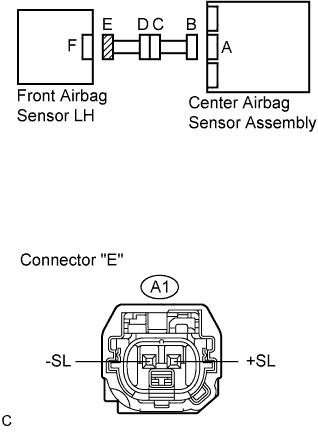 |
Disconnect the connectors from the center airbag sensor assembly and the front airbag sensor LH.
Connect the negative (-) terminal cable to the battery, and wait for at least 2 seconds.
Turn the engine switch on (IG).
Measure the voltage according to the value(s) in the table below.
| Tester connection | Condition | Specified condition |
| A1-2 (+SL) - Body ground | Engine switch on (IG) | Below 1 V |
| A1-1 (-SL) - Body ground | Engine switch on (IG) | Below 1 V |
|
| ||||
| OK | |
| 2.CHECK FRONT AIRBAG SENSOR LH CIRCUIT (SHORT) |
|
Turn the engine switch off.
Disconnect the negative (-) terminal cable from the battery, and wait for at least 90 seconds.
Measure the resistance according to the value(s) in the table below.
| Tester connection | Condition | Specified condition |
| A1-2 (+SL) - A1-1 (-SL) | Always | 1 MΩ or higher |
|
| ||||
| OK | |
| 3.CHECK FRONT AIRBAG SENSOR LH CIRCUIT (SHORT TO GROUND) |
|
Measure the resistance according to the value(s) in the table below.
| Tester connection | Condition | Specified condition |
| A1-2 (+SL) - Body ground | Always | 1 MΩ or higher |
| A1-1 (-SL) - Body ground | Always | 1 MΩ or higher |
|
| ||||
| OK | |
| 4.CHECK FRONT AIRBAG SENSOR RH CIRCUIT (SHORT TO B+) |
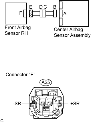 |
Disconnect the connector from the front airbag sensor RH.
Connect the negative (-) terminal cable to the battery, and wait for at least 2 seconds.
Turn the engine switch on (IG).
Measure the voltage according to the value(s) in the table below.
| Tester connection | Condition | Specified condition |
| A25-2 (+SR) - Body ground | Engine switch on (IG) | Below 1 V |
| A25-1 (+SR) - Body ground | Engine switch on (IG) | Below 1 V |
|
| ||||
| OK | |
| 5.CHECK FRONT AIRBAG SENSOR RH CIRCUIT (SHORT) |
|
Turn the engine switch off.
Disconnect the negative (-) terminal cable from the battery, and wait for at least 90 seconds.
Measure the resistance according to the value(s) in the table below.
| Tester connection | Condition | Specified condition |
| A25-2 (+SR) - A25-1 (-SR) | Always | 1 MΩ or higher |
|
| ||||
| OK | |
| 6.CHECK FRONT AIRBAG SENSOR RH CIRCUIT (SHORT TO GROUND) |
|
Measure the resistance according to the value(s) in the table below.
| Tester connection | Condition | Specified condition |
| A25-2 (+SR) - Body ground | Always | 1 MΩ or higher |
| A25-1 (-SR) - Body ground | Always | 1 MΩ or higher |
|
| ||||
| OK | |
| 7.CHECK CENTER AIRBAG SENSOR ASSEMBLY |
 |
Connect the connectors to the center airbag sensor assembly, front airbag sensor LH and RH.
Connect the negative (-) terminal cable to the battery, and wait for at least 2 seconds.
Turn the engine switch on (IG), and wait for at least 60 seconds.
Clear the DTCs stored in memory (Click here).
Turn the engine switch off.
Turn the engine switch on (IG), and wait for at least 60 seconds.
Check the DTCs (Click here).
|
| ||||
| OK | ||
| ||
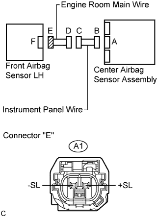
| 8.CHECK ENGINE ROOM MAIN WIRE (SHORT TO B+) |
 |
Turn the engine switch off.
Disconnect the negative (-) terminal cable from the battery, and wait for at least 90 seconds.
Disconnect the engine room main wire connector from the instrument panel wire.
Connect the negative (-) terminal cable to the battery, and wait for at least 2 seconds.
Turn the engine switch on (IG).
Measure the voltage according to the value(s) in the table below.
| Tester connection | Condition | Specified condition |
| A1-2 (+SL) - Body ground | Engine switch on (IG) | Below 1 V |
| A1-1 (-SL) - Body ground | Engine switch on (IG) | Below 1 V |
|
| ||||
| OK | ||
| ||
| 9.CHECK ENGINE ROOM MAIN WIRE (SHORT) |
|
Disconnect the engine room main wire connector from the instrument panel wire.
Measure the resistance according to the value(s) in the table below.
| Tester connection | Condition | Specified condition |
| A1-2 (+SL) - A1-1 (-SL) | Always | 1 MΩ or higher |
|
| ||||
| OK | ||
| ||
| 10.CHECK ENGINE ROOM MAIN WIRE (SHORT TO GROUND) |
|
Disconnect the engine room main wire connector from the instrument panel wire.
Measure the resistance according to the value(s) in the table below.
| Tester connection | Condition | Specified condition |
| A1-2 (+SL) - Body ground | Always | 1 MΩ or higher |
| A1-1 (-SL) - Body ground | Always | 1 MΩ or higher |
|
| ||||
| OK | ||
| ||
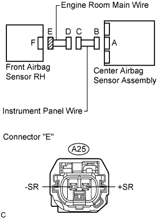
| 11.CHECK ENGINE ROOM MAIN WIRE (SHORT TO B+) |
 |
Turn the engine switch off.
Disconnect the negative (-) terminal cable from the battery, and wait for at least 90 seconds.
Disconnect the engine room main wire connector from the instrument panel wire.
Connect the negative (-) terminal cable to the battery, and wait for at least 2 seconds.
Turn the engine switch on (IG).
Measure the voltage according to the value(s) in the table below.
| Tester connection | Condition | Specified condition |
| A25-2 (+SR) - Body ground | Engine switch on (IG) | Below 1 V |
| A25-1 (-SR) - Body ground | Engine switch on (IG) | Below 1 V |
|
| ||||
| OK | ||
| ||
| 12.CHECK ENGINE ROOM MAIN WIRE (SHORT) |
|
Disconnect the engine room main wire connector from the instrument panel wire.
Measure the resistance according to the value(s) in the table below.
| Tester connection | Condition | Specified condition |
| A25-2 (+SR) - A25-1 (-SR) | Always | 1 MΩ or higher |
|
| ||||
| OK | ||
| ||
| 13.CHECK ENGINE ROOM MAIN WIRE (SHORT TO GROUND) |
|
Disconnect the engine room main wire connector from the instrument panel wire.
Measure the resistance according to the value(s) in the table below.
| Tester connection | Condition | Specified condition |
| A25-2 (+SR) - Body ground | Always | 1 MΩ or higher |
| A25-1 (-SR) - Body ground | Always | 1 MΩ or higher |
|
| ||||
| OK | ||
| ||
