DTC C1231/31 Steering Angle Sensor Circuit Malfunction |
| DTC No. | INF Code | DTC Detection Condition | Trouble Area |
| C1231/31 | - | When ECU IG1 terminal voltage is 10 V or more, the steering angle sensor malfunction signal is received. |
|
| 1.CHECK HARNESS AND CONNECTOR (MOMENTARY INTERRUPTION) |
Using the intelligent tester, check for any momentary interruption in the wire harness and connectors between the skid control ECU and the steering angle sensor (Click here).
| Item (Display) | Measurement Item / Range (Display) | Normal Condition |
| Steering Open | Steering sensor open detection / ERROR or NORMAL | ERROR: Momentary interruption NORMAL: Normal |
|
| ||||
| OK | |
| 2.CHECK DTC |
Clear the DTC (Click here).
Turn the engine switch off.
Turn the engine switch on (IG) again and check that no CAN communication system DTC is output.
Drive the vehicle and turn the steering wheel to the right and left at the speed of 24 mph (35 km/h) and check that no speed sensor and yaw rate sensor DTCs are output.
| Condition | Proceed To |
| No CAN communication system DTC and the speed sensor or yaw rate sensor DTC are output. | A |
| CAN communication system DTC is output. | B |
| Speed sensor or yaw rate sensor DTC is output. | C (Click here) |
|
| ||||
|
| ||||
| A | |
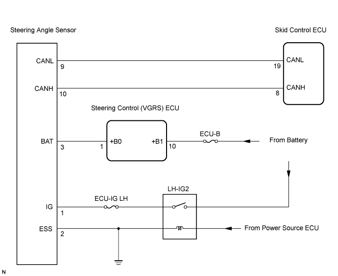
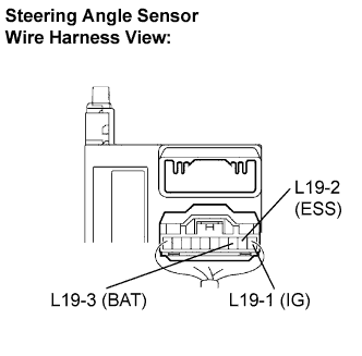
| 3.INSPECT STEERING ANGLE SENSOR (IG, BAT AND ESS TERMINAL) |
 |
Remove the steering wheel and the column cover lower.
Disconnect the steering angle sensor connector.
Measure the voltage according to the value(s) in the table below.
| Tester Connection | Condition | Specified Condition |
| L19-1 (IG) - Body ground | Engine switch on (IG) | 10 to 14 V |
| L19-3 (BAT) - Body ground | Always | 10 to 14 V |
Measure the resistance according to the value(s) in the table below.
| Tester Connection | Condition | Specified Condition |
| L19-2 (ESS) - Body ground | Engine switch off | Below 1 Ω |
|
| ||||
| OK | ||
| ||
| 4.REPAIR OR REPLACE HARNESS OR CONNECTOR (STEERING ANGLE SENSOR TO SKID CONTROL ECU) |
| NEXT | |
| 5.RECONFIRM DTC |
Clear the DTC (Click here).
Start the engine.
Drive the vehicle and turn the steering wheel to the right and left at the speed of 24 mph (35 km/h) or more.
Check if the same DTC is recorded (Click here).
| Condition | Proceed To |
| DTC (C1231/31) is not output | A |
| DTC (C1231/31) is output | B |
|
| ||||
| A | ||
| ||
