DTC C1202/68 Master Reservoir Level Malfunction |
| DTC No. | INF Code | DTC Detection Condition | Trouble Area |
| C1202/68 | - | The fluid level in the reservoir continues to drop when the pump motor is activated while braking.. |
|
| ↑ | 512 | An open in the switch signal circuit continues for 2 seconds or more. |
|
| 1.CHECK BRAKE FLUID LEVEL IN RESERVOIR |
Check that the brake fluid level is sufficient.
|
| ||||
| OK | |
| 2.INSPECT BRAKE FLUID LEVEL WARNING SWITCH |
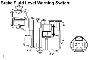 |
Disconnect the brake fluid level warning switch connector.
Measure the resistance according to the value(s) in the table below.
| Tester Connection | Condition | Specified Condition |
| 1 - 2 | Float up (Switch OFF) | 2 +- 0.16 kΩ |
| 1 - 2 | Float down (Switch ON) | Below 1 Ω |
|
| ||||
| OK | |
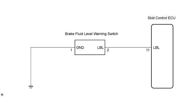
| 3.CHECK HARNESS AND CONNECTOR (SKID CONTROL ECU TO BRAKE FLUID LEVEL WARNING SWITCH) |
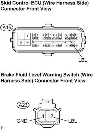 |
Disconnect the skid control ECU connector and brake fluid level warning switch connector.
Measure the resistance according to the value(s) in the table below.
| Tester Connection | Specified Condition |
| A15-11 (LBL) - A23-2 (LBL) | Below 1 Ω |
| A15-11 (LBL) - Body ground | 10 kΩ or higher |
| A23-1 (GND) - Body ground | Below 1 Ω |
|
| ||||
| OK | |
| 4.INSPECT SKID CONTROL ECU (SWITCH INPUT VOLTAGE) |
 |
Reconnect the skid control ECU connector.
Disconnect the brake fluid level warning switch connector.
Turn the engine switch on (IG).
Measure the voltage according to the value(s) in the table below.
| Tester Connection | Specified Condition |
| A23-2 - Body ground | 8 to 14 V |
|
| ||||
| OK | |
| 5.RECONFIRM DTC |
Clear the DTCs (Click here).
Turn the engine switch on (IG).
Check if the same DTC is recorded (Click here).
| Condition | Proceed To |
| DTC (C1202/68) is output | A |
| DTC (C1202/68) is not output | B |
|
| ||||
| A | ||
| ||
