DTC C1311/11 Open in Main Relay 1 Circuit |
DTC C1312/12 Short in Main Relay 1 Circuit |
DTC C1313/13 Open in Main Relay 2 Circuit |
DTC C1314/14 Short in Main Relay 2 Circuit |
| DTC No. | INF Code | DTC Detection Condition | Trouble Area |
| C311/11 | 1 | When either of the following is detected:
|
|
| C1312/12 | 3 | Relay contact is on (BS1 terminal is 6.5 V or more) for at least 4 seconds when main relay 1 is off. |
|
| C1313/13 | 4 | When any of the following is detected:
|
|
| C1314/14 | 6 | Relay contact is on (BS2 terminal is 6.5 V or more) for at least 4 sec. when main relay 2 is off. |
|
| 1.PERFORM ACTIVE TEST BY INTELLIGENT TESTER (ECB MAIN RELAY) |
Connect the intelligent tester to the DLC3.
Turn the engine switch on (IG).
Select the ACTIVE TEST mode on the intelligent tester.
| Item (Display) | Vehicle Condition / Test Details | Diagnostic Note |
| ECB Main Relay | Turns ECB main relay ON / OFF | Operation of relay (clicking sound) can be heard |
| ECB Main Relay 2 | Turns ECB main relay 2 ON / OFF | Operation of relay (clicking sound) can be heard |
Check the operation sound of the ECB main relay when operating it with the intelligent tester.
|
| ||||
| OK | |
| 2.INSPECT FUSE (ABS1 AND ABS MAIN FUSES) |
Remove the ABS1, ABS MAIN2 and ABS MAIN3 fuses from the engine room R/B (J/B) No.1.
Check the ABS1, ABS MAIN2 and ABS MAIN3 fuses.
|
| ||||
| OK | |
| 3.INSPECT ABS MAIN RELAY |
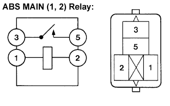 |
Remove the ABS MAIN1 relay and ABS MAIN2 relay.
Measure the resistance according to the value(s) in the table below.
| Tester Connection | Condition | Specified Condition |
| 3 - 5 | Always | 10 kΩ or higher (No continuity) |
| 3 - 5 | Apply B+ between terminal 1 and 2 | Below 1 Ω (Continuity) |
|
| ||||
| OK | |
| 4.INSPECT SKID CONTROL ECU (DI TERMINAL) |
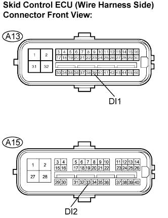 |
Disconnect the skid control ECU (A13, A15) connectors.
Measure the voltage according to the value(s) in the table below.
| Tester Connection | Specified Condition |
| A13-39 (DI1) - Body ground | 10 to 14 V |
| A15-33 (DI2) - Body ground | 10 to 14 V |
|
| ||||
| OK | |
| 5.CHECK HARNESS AND CONNECTOR (SKID CONTROL ECU TO ENGINE ROOM R/B NO.3) |
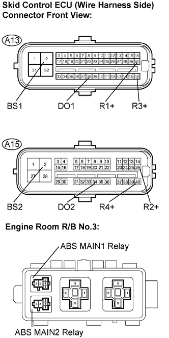 |
Disconnect the skid control ECU (A13, A15) connectors.
Remove the ABS MAIN1 relay and ABS MAIN2 relay.
Measure the resistance according to the value(s) in the table below.
| Tester Connection | Specified Condition |
| A13-2 (BS1) - ABS MAIN1 relay (3) | Below 1 Ω |
| A13-30 (R1+) - ABS MAIN1 relay (1) | Below 1 Ω |
| A13-38 (DO1) - ABS MAIN1 relay (5) | Below 1 Ω |
| A13-46 (R3+) - ABS MAIN1 relay (2) | Below 1 Ω |
| A15-2 (BS2) - ABS MAIN2 relay (3) | Below 1 Ω |
| A15-26 (R2+) - ABS MAIN2 relay (1) | Below 1 Ω |
| A15-34 (DO2) - ABS MAIN2 relay (5) | Below 1 Ω |
| A15-40 (R4+) - ABS MAIN2 relay (2) | Below 1 Ω |
Measure the resistance according to the value(s) in the table below.
| Tester Connection | Specified Condition |
| A13-2 (BS1) - Body ground | 10 kΩ or higher |
| A13-30 (R1+) - Body ground | 10 kΩ or higher |
| A13-38 (DO1) - Body ground | 10 kΩ or higher |
| A13-46 (R3+) - Body ground | 10 kΩ or higher |
| A15-2 (BS2) - Body ground | 10 kΩ or higher |
| A15-26 (R2+) - Body ground | 10 kΩ or higher |
| A15-34 (DO2) - Body ground | 10 kΩ or higher |
| A15-40 (R4+) - Body ground | 10 kΩ or higher |
|
| ||||
| OK | |
| 6.RECONFIRM DTC |
Clear the DTC (Click here).
Turn the engine switch on (IG).
Check if the same DTCs are recorded (Click here).
| Condition | Proceed To |
| DTCs (C1311/11, C1312/12, C1313/13 and C1314/14) are not output | A |
| DTCs (C1311/11, C1312/12, C1313/13 and C1314/14) are output | B |
|
| ||||
| A | ||
| ||
