DTC C1315/31 SMC1 Changeover Solenoid Malfunction |
DTC C1316/32 SMC2 Changeover Solenoid Malfunction |
DTC C1352/21 Front Increasing Pressure Solenoid RH Malfunction |
DTC C1353/23 Front Increasing Pressure Solenoid LH Malfunction |
DTC C1354/25 Rear Increasing Pressure Solenoid RH Malfunction |
DTC C1355/27 Rear Increasing Pressure Solenoid LH Malfunction |
DTC C1356/22 Front Decreasing Pressure Solenoid RH Malfunction |
DTC C1357/24 Front Decreasing Pressure Solenoid LH Malfunction |
DTC C1358/26 Rear Decreasing Pressure Solenoid RH Malfunction |
DTC C1359/28 Rear Decreasing Pressure Solenoid LH Malfunction |
| DTC No. | INF Code | DTC Detection Condition | Trouble Area |
| C1315/31 | 61 | When either of the following is detected:
|
|
| ↑ | 62 | Current leaks for 0.05 seconds or more when SMC1 is off. | ↑ |
| ↑ | 63 | Open circuit in SMC1 continues for 0.05 seconds or more. | ↑ |
| ↑ | 64 | Overcurrent in SMC1 continues for 0.05 seconds or more. | ↑ |
| C1316/32 | 66 | When either of the following is detected:
|
|
| ↑ | 67 | Open circuit in SMC2 continues for 0.05 seconds or more when SMC2 is off. | ↑ |
| ↑ | 68 | Open circuit in SMC2 continues for 0.05 seconds or more. | ↑ |
| ↑ | 69 | Overcurrent in SMC2 continues for 0.05 seconds or more. | ↑ |
| C1352/21 | 11 | Open circuit in SLAFR continues for 0.05 seconds or more when SLAFR is off. |
|
| ↑ | 12 | Open circuit in SLAFR continues for 0.05 seconds or more when SLAFR is on. | ↑ |
| ↑ | 13 | Short to +B or voltage leak in SLAFR continues for 0.05 seconds or more. | ↑ |
| ↑ | 14 | Overcurrent in SLAFR continues for 0.05 seconds or more. | ↑ |
| C1353/23 | 21 | Open circuit in SLAFL continues for 0.05 seconds or more when SLAFL is off. |
|
| ↑ | 22 | Open circuit in SLAFL continues for 0.05 seconds or more when SLAFL is on. | ↑ |
| ↑ | 23 | Short to +B or voltage leak in SLAFL continues for 0.05 seconds or more. | ↑ |
| ↑ | 24 | Overcurrent in SLAFL continues for 0.05 seconds or more. | ↑ |
| C1354/25 | 31 | Open circuit in SLARR continues for 0.05 seconds or more when SLARR is off. |
|
| ↑ | 32 | Open circuit in SLARR continues for 0.05 seconds or more when SLARR is on. | ↑ |
| ↑ | 33 | Short to +B or voltage leak in SLARR continues for 0.05 seconds or more. | ↑ |
| ↑ | 34 | Overcurrent in SLARR continues for 0.05 seconds or more. | ↑ |
| C1355/27 | 41 | Open circuit in SLARL continues for 0.05 seconds or more when SLARL is off. |
|
| ↑ | 42 | Open circuit in SLARL continues for 0.05 seconds or more when SLARL is on. | ↑ |
| ↑ | 43 | Short to +B or voltage leak in SLARL continues for 0.05 seconds or more. | ↑ |
| ↑ | 44 | Overcurrent in SLARL continues for 0.05 seconds or more. | ↑ |
| C1356/22 | 16 | Open circuit in SLRFR continues for 0.05 seconds or more when SLRFR is off. |
|
| ↑ | 17 | Open circuit in SLRFR continues for 0.05 seconds or more when SLRFR is on. | ↑ |
| ↑ | 18 | Short to +B or voltage leak in SLRFR continues for 0.05 seconds or more. | ↑ |
| ↑ | 19 | Overcurrent in SLRFR continues for 0.05 seconds or more. | ↑ |
| C1357/24 | 26 | Open circuit in SLRFL continues for 0.05 seconds or more when SLRFL is off. |
|
| ↑ | 27 | Open circuit in SLRFL continues for 0.05 seconds or more when SLRFL is on. | ↑ |
| ↑ | 28 | Short to +B or voltage leak in SLRFL continues for 0.05 seconds or more. | ↑ |
| ↑ | 29 | Overcurrent in SLRFL continues for 0.05 seconds or more. | ↑ |
| C1358/26 | 36 | Open circuit in SLRRR continues for 0.05 seconds or more when SLRRR is off. |
|
| ↑ | 37 | Open circuit in SLRRR continues for 0.05 seconds or more when SLRRR is on. | ↑ |
| ↑ | 38 | Short to +B or voltage leak in SLRRR continues for 0.05 seconds or more. | ↑ |
| ↑ | 39 | Overcurrent in SLRRR continues for 0.05 seconds or more. | ↑ |
| C1359/29 | 46 | Open circuit in SLRRL continues for 0.05 seconds or more when SLRRL is off. |
|
| ↑ | 47 | Open circuit in SLRRL continues for 0.05 seconds or more when SLRRL is on. | ↑ |
| ↑ | 48 | Short to +B or voltage leak in SLRRL continues for 0.05 seconds or more. | ↑ |
| ↑ | 49 | Overcurrent in SLRRL continues for 0.05 seconds or more. | ↑ |
| 1.INSPECT BRAKE ACTUATOR ASSEMBLY |
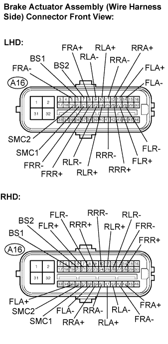 |
Disconnect the brake actuator assembly connector.
Measure the resistance according to the value(s) in the table below.
| Tester Connection | Specified Condition |
| A16-20 (SMC1) - A16-6 (BS1) | 15.3 to 25.0 Ω |
| A16-19 (SMC2) - A16-7 (BS2) | 15.3 to 25.0 Ω |
| A16-8 (FRA+) - A16-5 (FRA-) | 3.6 to 6.0 Ω |
| A16-22 (FRR+) - A16-21 (FRR-) | 3.6 to 6.0 Ω |
| A16-13 (FLA+) - A16-14 (FLA-) | 3.6 to 6.0 Ω |
| A16-27 (FLR+) - A16-28 (FLR-) | 3.6 to 6.0 Ω |
| A16-12 (RRA+) - A16-11 (RRA-) | 3.6 to 6.0 Ω |
| A16-10 (RLA+) - A16-9 (RLA-) | 3.6 to 6.0 Ω |
| A16-26 (RRR+) - A16-25 (RRR-) | 4.4 to 7.0 Ω |
| A16-24 (RLR+) - A16-23 (RLR-) | 4.4 to 7.0 Ω |
| Tester Connection | Specified Condition |
| A16-37 (SMC1) - A16-19 (BS1) | 15.3 to 25.0 Ω |
| A16-36 (SMC2) - A16-20 (BS2) | 15.3 to 25.0 Ω |
| A16-44 (FRA+) - A16-43 (FRA-) | 3.6 to 6.0 Ω |
| A16-28 (FRR+) - A16-27 (FRR-) | 3.6 to 6.0 Ω |
| A16-35 (FLA+) - A16-43 (FLA-) | 3.6 to 6.0 Ω |
| A16-21 (FLR+) - A16-22 (FLR-) | 3.6 to 6.0 Ω |
| A16-39 (RRA+) - A16-40 (RRA-) | 3.6 to 6.0 Ω |
| A16-41 (RLA+) - A16-42 (RLA-) | 3.6 to 6.0 Ω |
| A16-23 (RRR+) - A16-24 (RRR-) | 4.4 to 7.0 Ω |
| A16-25 (RLR+) - A16-26 (RLR-) | 4.4 to 7.0 Ω |
|
| ||||
| OK | |
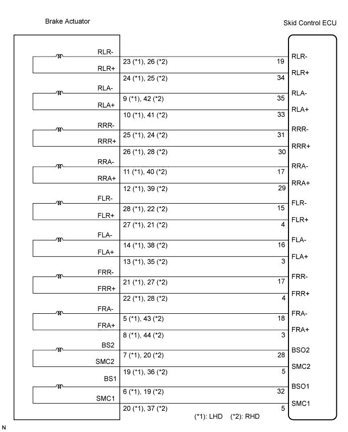
| 2.CHECK HARNESS AND CONNECTOR (SKID CONTROL ECU TO BRAKE ACTUATOR ASSEMBLY) |
 |
Disconnect the skid control ECU (A13, A15) connectors and brake actuator assembly connector.
Measure the resistance according to the value(s) in the table below.
| Tester Connection | Specified Condition |
| A13-5 (SMC1) - A16-20 (SMC1) | Below 1 Ω |
| A13-32 (BSO1) - A16-6 (BS1) | Below 1 Ω |
| A13-3 (FRA+) - A16-8 (FRA+) | Below 1 Ω |
| A13-18 (FRA-) - A16-5 (FRA-) | Below 1 Ω |
| A13-4 (FRR+) - A16-22 (FRR+) | Below 1 Ω |
| A13-17 (FRR-) - A16-21 (FRR-) | Below 1 Ω |
| A13-33 (RLA+) - A16-10 (RLA+) | Below 1 Ω |
| A13-35 (RLA-) - A16-9 (RLA-) | Below 1 Ω |
| A13-34 (RLR+) - A16-24 (RLR+) | Below 1 Ω |
| A13-19 (RLR-) - A16-23 (RLR-) | Below 1 Ω |
| A15-5 (SMC2) - A16-19 (SMC2) | Below 1 Ω |
| A15-28 (BSO2) - A16-7 (BS2) | Below 1 Ω |
| A15-3 (FLA+) - A16-13 (FLA+) | Below 1 Ω |
| A15-16 (FLA-) - A16-14 (FLA-) | Below 1 Ω |
| A15-4 (FLR+) - A16-27 (FLR+) | Below 1 Ω |
| A15-15 (FLR-) - A16-28 (FLR-) | Below 1 Ω |
| A15-29 (RRA+) - A16-12 (RRA+) | Below 1 Ω |
| A15-17 (RRA-) - A16-11 (RRA-) | Below 1 Ω |
| A15-30 (RRR+) - A16-26 (RRR+) | Below 1 Ω |
| A15-31 (RRR-) - A16-25 (RRR-) | Below 1 Ω |
| Tester Connection | Specified Condition |
| A13-5 (SMC1) - A16-37 (SMC1) | Below 1 Ω |
| A13-32 (BSO1) - A16-19 (BS1) | Below 1 Ω |
| A13-3 (FRA+) - A16-44 (FRA+) | Below 1 Ω |
| A13-18 (FRA-) - A16-43 (FRA-) | Below 1 Ω |
| A13-4 (FRR+) - A16-28 (FRR+) | Below 1 Ω |
| A13-17 (FRR-) - A16-27 (FRR-) | Below 1 Ω |
| A13-33 (RLA+) - A16-41 (RLA+) | Below 1 Ω |
| A13-35 (RLA-) - A16-42 (RLA-) | Below 1 Ω |
| A13-34 (RLR+) - A16-25 (RLR+) | Below 1 Ω |
| A13-19 (RLR-) - A16-26 (RLR-) | Below 1 Ω |
| A15-5 (SMC2) - A16-36 (SMC2) | Below 1 Ω |
| A15-28 (BSO2) - A16-20 (BS2) | Below 1 Ω |
| A15-3 (FLA+) - A16-35 (FLA+) | Below 1 Ω |
| A15-16 (FLA-) - A16-43 (FLA-) | Below 1 Ω |
| A15-4 (FLR+) - A16-21 (FLR+) | Below 1 Ω |
| A15-15 (FLR-) - A16-22 (FLR-) | Below 1 Ω |
| A15-29 (RRA+) - A16-39 (RRA+) | Below 1 Ω |
| A15-17 (RRA-) - A16-40 (RRA-) | Below 1 Ω |
| A15-30 (RRR+) - A16-23 (RRR+) | Below 1 Ω |
| A15-31 (RRR-) - A16-24 (RRR-) | Below 1 Ω |
Measure the resistance according to the value(s) in the table below.
| Tester Connection | Specified Condition |
| A13-5 (SMC1)) - Body ground | 10 kΩ or higher |
| A13-32 (BSO1) - Body ground | 10 kΩ or higher |
| A13-3 (FRA+) - Body ground | 10 kΩ or higher |
| A13-18 (FRA-) - Body ground | 10 kΩ or higher |
| A13-4 (FRR+) - Body ground | 10 kΩ or higher |
| A13-17 (FRR-) - Body ground | 10 kΩ or higher |
| A13-33 (RLA+) - Body ground | 10 kΩ or higher |
| A13-35 (RLA-) - Body ground | 10 kΩ or higher |
| A13-34 (RLR+) - Body ground | 10 kΩ or higher |
| A13-19 (RLR-) - Body ground | 10 kΩ or higher |
| A15-5 (SMC2) - Body ground | 10 kΩ or higher |
| A15-28 (BSO2) - Body ground | 10 kΩ or higher |
| A15-3 (FLA+) - Body ground | 10 kΩ or higher |
| A15-16 (FLA-) - Body ground | 10 kΩ or higher |
| A15-4 (FLR+) - Body ground | 10 kΩ or higher |
| A15-15 (FLR-) - Body ground | 10 kΩ or higher |
| A15-29 (RRA+) - Body ground | 10 kΩ or higher |
| A15-17 (RRA-) - Body ground | 10 kΩ or higher |
| A15-30 (RRR+) - Body ground | 10 kΩ or higher |
| A15-31 (RRR-) - Body ground | 10 kΩ or higher |
|
| ||||
| OK | |
| 3.RECONFIRM DTC |
Clear the DTC (Click here).
Turn the engine switch on (IG).
Check if the same DTCs are recorded (Click here).
| Condition | Proceed To |
| DTCs (C1315/31, C1316/32, C1352/21, C1353/23, C1354/25, C1355/27, C1356/22, C1357/24, C1358/26 and C1359/28) are not output | A |
| DTCs (C1315/31, C1316/32, C1352/21, C1353/23, C1354/25, C1355/27, C1356/22, C1357/24, C1358/26 and C1359/28) are output | B |
|
| ||||
| A | ||
| ||
