DTC C1341/62 Front Hydraulic System RH Malfunction |
DTC C1342/63 Front Hydraulic System LH Malfunction |
DTC C1343/64 Rear Hydraulic System RH Malfunction |
DTC C1344/65 Rear Hydraulic System LH Malfunction |
| DTC No. | INF Code | DTC Detection Condition | Trouble Area |
| C1341/62 | 551 552 | Hydraulic pressure control on FR wheel has deteriorated. |
|
| ↑ | 553 | There is a malfunction, such as leakage in the pressure increase control valve of FR wheel. |
|
| ↑ | 554 555 | There is a malfunction, such as leakage in the pressure decrease control valve of FR wheel. | ↑ |
| C1342/63 | 561 562 | Hydraulic pressure control on FL wheel has deteriorated. |
|
| ↑ | 563 | There is a malfunction, such as leakage in pressure increase control valve of FL wheel. |
|
| ↑ | 564 565 | There is a malfunction, such as leakage in pressure decrease control valve of FL wheel. | ↑ |
| C1343/64 | 571 572 | Hydraulic pressure control on RR wheel has deteriorated. |
|
| ↑ | 573 | There is a malfunction, such as leakage in pressure increase control valve of RR wheel. |
|
| ↑ | 574 575 | There is a malfunction, such as leakage in pressure decrease control valve of RR wheel. | ↑ |
| C1344/65 | 581 582 | Hydraulic pressure control on RL wheel has deteriorated. |
|
| ↑ | 583 | There is a malfunction, such as leakage in pressure increase control valve of RL wheel. |
|
| ↑ | 584 585 | There is a malfunction, such as leakage in pressure decrease control valve of RL wheel. | ↑ |
| 1.CHECK BRAKE FLUID LEAKAGE |
Check that there is no fluid leakage in the brake line between the brake actuator and the wheel cylinder which is the cause of DTCs.
Check that the brake is not dragging.
|
| ||||
| OK | |
| 2.PERFORM AIR BLEED |
Bleed the air from the front and rear brake systems (Click here).
| NEXT | |
| 3.CHECK HARNESS AND CONNECTOR (SKID CONTROL ECU TO BODY GROUND) |
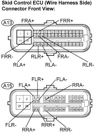 |
Disconnect the skid control ECU (A13, A15) connectors.
Measure the resistance according to the value(s) in the table below.
| Tester Connection | Specified Condition |
| A13-3 (FRA+) - Body ground | 10 kΩ or higher |
| A13-18 (FRA-) - Body ground | 10 kΩ or higher |
| A13-4 (FRR+) - Body ground | 10 kΩ or higher |
| A13-17 (FRR-) - Body ground | 10 kΩ or higher |
| A13-33 (RLA+) - Body ground | 10 kΩ or higher |
| A13-35 (RLA-) - Body ground | 10 kΩ or higher |
| A13-34 (RLR+) - Body ground | 10 kΩ or higher |
| A13-19 (RLR-) - Body ground | 10 kΩ or higher |
| A15-3 (FLA+) - Body ground | 10 kΩ or higher |
| A15-16 (FLA-) - Body ground | 10 kΩ or higher |
| A15-4 (FLR+) - Body ground | 10 kΩ or higher |
| A15-15 (FLR-) - Body ground | 10 kΩ or higher |
| A15-29 (RRA+) - Body ground | 10 kΩ or higher |
| A15-17 (RRA-) - Body ground | 10 kΩ or higher |
| A15-30 (RRR+) - Body ground | 10 kΩ or higher |
| A15-31 (RRR-) - Body ground | 10 kΩ or higher |
|
| ||||
| OK | |
| 4.READ VALUE OF INTELLIGENT TESTER (WHEEL CYLINDER PRESSURE SENSOR) |
Connect the pedal effort gauge.
Install the LSPV gauge (SST) and perform bleeding (Click here).
Connect the intelligent tester to the DLC3.
Select the DATA LIST mode on the intelligent tester.
| Item (Display) | Measurement Item / Range (Display) | Normal Condition |
| FR W/C Sensor | FR wheel cylinder pressure sensor / min.: 0 V, max.: 5 V | When brake pedal is released: 0.3 to 0.9 V |
| FL W/C Sensor | FL wheel cylinder pressure sensor / min.: 0 V, max.: 5 V | When brake pedal is released: 0.3 to 0.9 V |
| RR W/C Sensor | RR wheel cylinder pressure sensor / min.: 0 V, max.: 5 V | When brake pedal is released: 0.3 to 0.9 V |
| RL W/C Sensor | RL wheel cylinder pressure sensor / min.: 0 V, max.: 5 V | When brake pedal is released: 0.3 to 0.9 V |
Check the output value of the wheel cylinder pressure at each fluid pressure during the ECB control.
| Fluid Pressure MPa (kgf/cm2, psi) | FR W/C Sensor (DATA LIST) | FL W/C Sensor (DATA LIST) |
| 3.2 (32.6, 464) | 1.0 to 1.3 V | 1.0 to 1.3 V |
| 7.0 (71.4, 1016) | 1.75 to 2.05 V | 1.75 to 2.05 V |
| 8.3 (84.6, 1203) | 2.05 to 2.35 V | 2.05 to 2.35 V |
| Fluid Pressure MPa (kgf/cm2, psi) | RR W/C Sensor (DATA LIST) | RL W/C Sensor (DATA LIST) |
| 3.1 (31.6, 449) | 1.0 to 1.3 V | 1.0 to 1.3 V |
| 4.0 (40.8, 580) | 1.15 to 1.45 V | 1.15 to 1.45 V |
|
| ||||
| OK | |
| 5.CHECK BRAKE DISC |
Disconnect the brake pedal stroke sensor connector.
Carry out the running and braking test according to freeze frame data or customer problem analysis. Check the brake line pressure vibration caused due to uneven wear of the disc according to brake pedal vibration.
|
| ||||
| OK | |
| 6.RECONFIRM DTC |
Clear the DTCs (Click here).
Repeat the braking test under malfunction conditions recreated based on the FREEZE FRAME DATA or customer problem analysis.
Check if the same DTCs are recorded (Click here).
| Condition | Proceed To |
| DTCs (C1341/62, C1342/63, C1343/64 and C1344/65) are not output | A |
| DTCs (C1341/62, C1342/63, C1343/64 and C1344/65) are output | B |
|
| ||||
| A | ||
| ||
