DTC C1365/54 Accumulator Pressure Sensor Malfunction |
| DTC No. | INF Code | DTC Detection Condition | Trouble Area |
| C1365/54 | 211 | Sensor power 1 (VCM1) voltage is 4.7 V or less or 5.3 V or more for at least 0.05 seconds. |
|
| ↑ | 212 | Accumulator pressure sensor output voltage (PAC1) is less than 0.25 or 4.5 V or more for at least 0.05 seconds. | ↑ |
| ↑ | 214 | While the motor is OFF, the total of the wheel cylinder pressure sensor values of all 4 wheels increases but the accumulator pressure changes little for 0.5 seconds or more. | ↑ |
| ↑ | 215 | The accumulator pressure sensor output voltage (PAC1) is stuck at 4.7 V or less. | ↑ |
| 1.CHECK HARNESS AND CONNECTOR (SKID CONTROL ECU TO BRAKE ACTUATOR ASSEMBLY) |
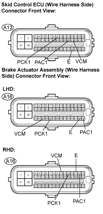 |
Disconnect the skid control ECU and brake actuator assembly connector.
Measure the resistance according to the value(s) in the table below.
| Tester Connection | Specified Condition |
| A13-9 (PCK1) - A16-37 (PCK1) | Below 1 Ω |
| A13-26 (PAC1) - A16-46 (PAC1) | Below 1 Ω |
| A13-27 (VCM) - A16-35 (VCM) | Below 1 Ω |
| A13-43 (E) - A16-45 (E) | Below 1 Ω |
| Tester Connection | Specified Condition |
| A13-9 (PCK1) - A16-12 (PCK1) | Below 1 Ω |
| A13-26 (PAC1) - A16-15 (PAC1) | Below 1 Ω |
| A13-27 (VCM) - A16-10 (VCM) | Below 1 Ω |
| A13-43 (E) - A16-14 (E) | Below 1 Ω |
Measure the resistance according to the value(s) in the table below.
| Tester Connection | Specified Condition |
| A13-9 (PCK1) - Body ground | 10 kΩ or higher |
| A13-26 (PAC1) - Body ground | 10 kΩ or higher |
| A13-27 (VCM) - Body ground | 10 kΩ or higher |
| A13-43 (E) - Body ground | 10 kΩ or higher |
|
| ||||
| OK | |
| 2.RECONFIRM DTC |
Clear the DTC (Click here).
Turn the engine switch on (IG).
Check if the same DTC is recorded (Click here).
| Condition | Proceed To |
| DTC (C1365/54) is output | A |
| DTC (C1365/54) is not output | B |
|
| ||||
| A | |
| 3.CHECK FREEZE FRAME DATA |
Check the INF code from the FREEZE FRAME DATA memorized when the DTC (C1365/54) is stored (Click here).
| Condition | Proceed To |
| Sensor power supply voltage trouble (211) codes are output | A |
| Sensor output value trouble (212, 214 and 215) codes are output | B |
|
| ||||
| A | ||
| ||
