DTC C1377/43 Capacitor Malfunction |
| DTC No. | INF Code | DTC Detection Condition | Trouble Area |
| C1377/43 | 101 | Brake control power supply assembly is deteriorated (indicates a need to replace). | Brake control power supply |
| ↑ | 102 | Self-discharge (current leak) is excessive (internal malfunction). | ↑ |
| ↑ | 103 | Overvoltage (16.4 V or more) continues to be applied from the battery to the brake control power supply voltage input (+BC) for 10 seconds or more. | Apply high voltage |
| ↑ | 105 | Circuit inside the power back up unit (charge) is malfunctioning. | Brake control power supply |
| ↑ | 106 | Circuit inside the power back up unit (back up output circuit) is malfunctioning. | ↑ |
| ↑ | 107 | Malfunction in the forced discharge circuit. | ↑ |
| ↑ | 108 | Circuit inside the power back up unit (voltage monitor circuit) is malfunctioning. | ↑ |
| ↑ | 109 | Open circuit between battery (12 V) and brake control power supply power input (+BC terminal). |
|
| ↑ | 110 | When either of the following is detected:
|
|
| 1.CHECK FREEZE FRAME DATA |
Check the INF code from the FREEZE FRAME DATA memorized when the DTC (C1377/43) is stored (Click here).
| Condition | Proceed To |
| INF codes (109, and 110) are output | A |
| INF codes (101, 102, 105, 106, 107, and 108) are output | B |
| INF code (103) is output | C |
|
| ||||
|
| ||||
| A | |
| 2.INSPECT FUSE (ABS1 AND ABS MAIN1 FUSES) |
Remove the ABS1 and ABS MAIN1 fuses from the engine room R/B (J/B) No.1.
Check the ABS1 and ABS MAIN1 fuses.
|
| ||||
| OK | |
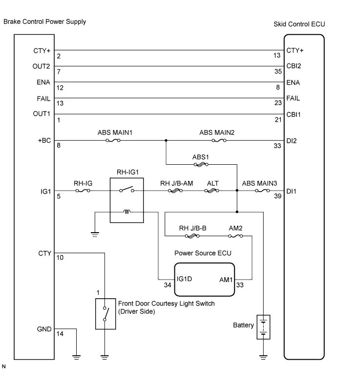
| 3.INSPECT BRAKE CONTROL POWER SUPPLY (+BC AND GND TERMINAL) |
 |
Disconnect the brake control power supply connector.
Measure the voltage according to the value(s) in the table below.
| Tester Connection | Specified Condition |
| V27-8 (+BC) - Body ground | 10 to 14 V |
Measure the resistance according to the value(s) in the table below.
| Tester Connection | Specified Condition |
| V27-14 (GND) - Body ground | Below 1 Ω |
|
| ||||
| OK | |
| 4.INSPECT SKID CONTROL ECU (DI TERMINAL) |
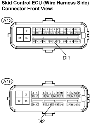 |
Disconnect the skid control ECU (A13, A15) connectors.
Measure the voltage according to the value(s) in the table below.
| Tester Connection | Specified Condition |
| A13-39 (DI1) - Body ground | 10 to 14 V |
| A15-33 (DI2) - Body ground | 10 to 14 V |
|
| ||||
| OK | |
| 5.INSPECT BRAKE CONTROL POWER SUPPLY (CTY+ AND OUT TERMINAL) |
 |
Measure the voltage according to the value(s) in the table below.
| Tester Connection | Specified Condition |
| V27-1 (OUT1) - Body ground | 10 to 14 V |
| V27-2 (CTY+) - Body ground | 10 to 14 V (*1) |
| V27-7 (OUT2) - Body ground | 10 to 14 V |
|
| ||||
| NG | |
| 6.CHECK HARNESS AND CONNECTOR (SKID CONTROL ECU TO BRAKE CONTROL POWER SUPPLY) |
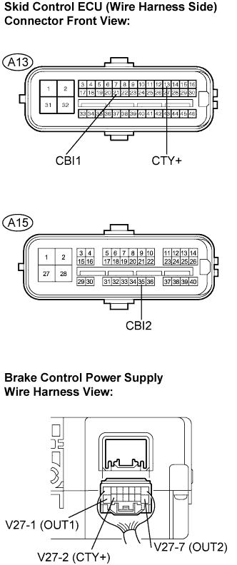 |
Disconnect the skid control ECU (A13, A15) connectors and brake control power supply connector.
Measure the resistance according to the value(s) in the table below.
| Tester Connection | Specified Condition |
| A13-13 (CTY+) - V27-2 (CTY+) | Below 1 Ω |
| A13-21 (CBI1) - V27-1 (OUT1) | Below 1 Ω |
| A15-35 (CBI2) - V27-7 (OUT2) | Below 1 Ω |
Measure the resistance according to the value(s) in the table below.
| Tester Connection | Specified Condition |
| A13-13 (CTY+) - Body ground | 10 kΩ or higher |
| A13-21 (CBI1) - Body ground | 10 kΩ or higher |
| A15-35 (CBI2) - Body ground | 10 kΩ or higher |
|
| ||||
| NG | ||
| ||
| 7.INSPECT BATTERY |
Check the battery voltage.
|
| ||||
| OK | |
| 8.INSPECT BRAKE CONTROL POWER SUPPLY (+BC TERMINAL) |
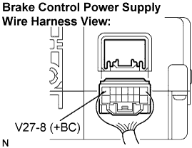 |
Disconnect the brake control power supply connector.
Measure the voltage according to the value(s) in the table below.
| Tester Connection | Specified Condition |
| V27-8 (+BC) - Body ground | 10 to 14 V |
|
| ||||
| OK | |
| 9.RECONFIRM DTC |
Clear the DTC (Click here).
Turn the engine switch on (IG).
Check if the same DTC is recorded (Click here).
| Condition | Proceed To |
| DTC (C1377/43) is not output | A |
| DTC (C1377/43) is output | B |
|
| ||||
| A | ||
| ||
