AIR CONDITIONING SYSTEM > Low Pressure Sensor Circuit |

| 1.INSPECT REFRIGERANT PRESSURE |
Install the manifold gauge set.
Check that refrigerant is filled in the system by checking the manifold gauge set's pressure readings.
|
| ||||
| OK | |
| 2.CHECK WIRE HARNESS (LOW PRESSURE SENSOR - A/C AMPLIFIER) |
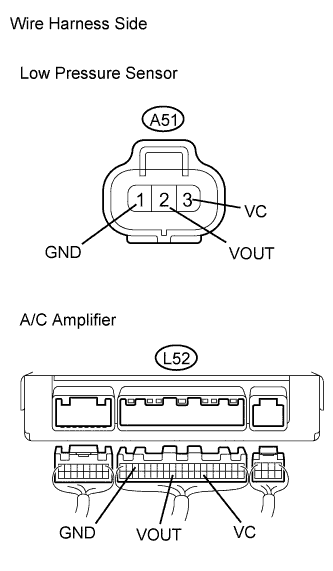 |
Disconnect the A51 low pressure sensor connector.
Disconnect the L52 A/C amplifier connector.
Measure the resistance of the wire harness side connectors.
| Tester Connection | Condition | Specified Condition |
| A51-1 (GND) - L52-18 (GND) | Always | Below 1 Ω |
| A51-2 (VOUT) - L52-32 (VOUT) | Always | Below 1 Ω |
| A51-3 (VC) - L52-27 (VC) | Always | Below 1 Ω |
| L52-18 (GND) - Body ground | Always | 10 kΩ or higher |
| L52-32 (VOUT) - Body ground | Always | 10 kΩ or higher |
| L52-27 (VC) - Body ground | Always | 10 kΩ or higher |
|
| ||||
| OK | |
| 3.CHECK AIR CONDITIONING AMPLIFIER |
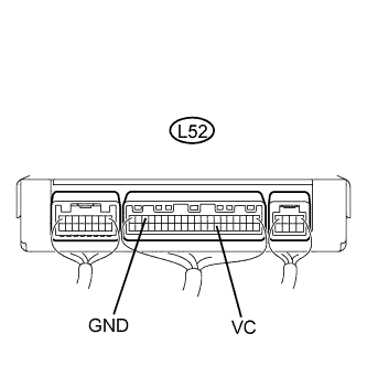 |
Remove the A/C amplifier with its connectors still connected.
Measure the resistance of the connector.
| Tester Connection | Condition | Specified Condition |
| L52-18 (GND) - Body ground | Always | Below 1 Ω |
Measure the voltage of the connector.
| Tester Connection | Condition | Specified Condition |
| L52-27 (VC) - Body ground | Engine switch on (IG) | 10 to 14 V |
| Engine switch off | Below 1 V |
|
| ||||
| OK | |
| 4.INSPECT LOW PRESSURE SENSOR |
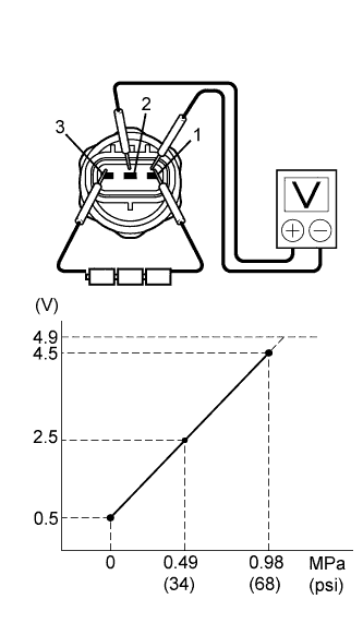 |
Install the manifold gauge set.
Connect the three 1.5 V dry cell batteries' positive (+) lead to terminal 3 and the negative (-) lead to terminal 1. Then connect the voltmeter's positive (+) lead to terminal 2 and negative (-) lead to terminal 1. Measure the voltage.
|
| ||||
| OK | ||
| ||
