DTC C2121/21 No Signal from Transmitter ID1 in Main Mode |
DTC C2122/22 No Signal from Transmitter ID2 in Main Mode |
DTC C2123/23 No Signal from Transmitter ID3 in Main Mode |
DTC C2124/24 No Signal from Transmitter ID4 in Main Mode |
DTC C2131/31 No Signal from Transmitter ID1 in 2nd Mode |
DTC C2132/32 No Signal from Transmitter ID2 in 2nd Mode |
DTC C2133/33 No Signal from Transmitter ID3 in 2nd Mode |
DTC C2134/34 No Signal from Transmitter ID4 in 2nd Mode |
DTC C2181/81 Transmitter ID1 not Received (Test Mode DTC) |
DTC C2182/82 Transmitter ID2 not Received (Test Mode DTC) |
DTC C2183/83 Transmitter ID3 not Received (Test Mode DTC) |
DTC C2184/84 Transmitter ID4 not Received (Test Mode DTC) |
| DTC No. | DTC Detecting Condition | Trouble Area |
| C2121/21 C2122/22 C2123/23 C2124/24 C2131/31 C2132/32 C2133/33 C2134/34 | These DTCs are detected when no signals are received for 51 minutes or more, after a vehicle speed of 5 mph (8 km/h) or more is detected and no signals are still received for 12 minutes or more. |
|
| C2181/81 C2182/82 C2183/83 C2184/84 | Malfunction in the transmitting/receiving circuit |
|

| 1.CHECK TIRE PRESSURE WARNING LIGHT |
Turn the engine switch on (IG).
Check the tire pressure warning light.
| Proceed to | Condition |
| A | Does not blink |
| B | Comes on and goes off repeatedly at 0.5 second intervals |
|
| ||||
| A | |
| 2.CLEAR DTC |
| NEXT | |
| 3.CHECK DTC |
Check for DTC.
|
| ||||
| OK | ||
| ||
| 4.CHECK DTC |
Is DTC C2121/21, C2122/22, C2123/23 and C2124/24 output?
|
| ||||
| YES | |
| 5.CHECK DTC |
Are DTCs C2121/21, C2122/22, C2123 and C2124 all output?
|
| ||||
| YES | |
| 6.CHECK TIRE PRESSURE WARNING SWITCH MAIN POSITION |
|
| ||||
| OK | |
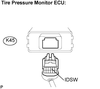
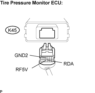
| 7.INSPECT TIRE PRESSURE MONITOR ECU |
 |
Connect the tire pressure monitor ECU K45 connector.
Measure the voltage according to the value(s) in the table below.
| Tester Connection | Condition | Specified Condition |
| K45-10 (RF5V) - K45-4 ((GND2) | Engine Switch on (IG) | 4.5 to 5.5 V |
|
| ||||
| NG | |
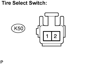
| 8.CHECK HARNESS AND CONNECTOR (TIRE PRESSURE MONITOR ECU - TIRE SELECT SWITCH)) |
 |
Disconnect the tire pressure monitor ECU K45 connector and tire select switch K50 connector.
 |
Measure the resistance according to the value(s) in the table below.
| Tester Connection | Specified Condition |
| K45-3 (IDSW) - K50-2 | Below 1 Ω |
| K45-3 (IDSW) - Body ground | 10 kΩ or higher |
|
| ||||
| OK | |
| 9.INSPECT TIRE SELECT SWITCH |
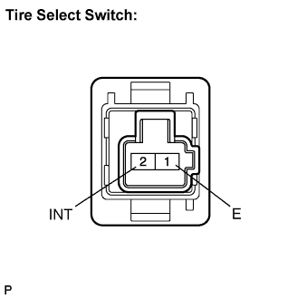 |
Disconnect tire select switch K50 connector.
Measure the resistance according to the value(s) in the table below.
| Switch Position | Tester Connection | Specified Condition |
| MAIN | 2 (INT) - 1 (E) | 10 kΩ or higher |
| 2nd | 2 (INT) - 1 (E) | Below 1 Ω |
|
| ||||
| OK | ||
| ||
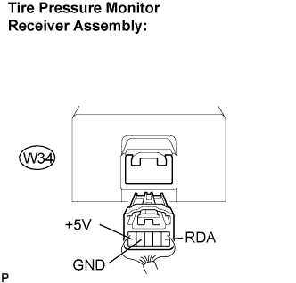
| 10.CHECK HARNESS AND CONNECTOR (TIRE MONITOR RECEIVER ASSEMBLY - TIRE MONITOR ECU) |
 |
Disconnect the tire pressure monitor receiver assembly W34 connector and tire pressure monitor ECU K45 connector.
 |
Measure the resistance according to the value(s) in the table below.
| Tester Connection | Specified Condition |
| K45-9 (RDA) - W34-1 (RDA) | Below 1Ω |
| K45-10 (RF5V) - W34-5 (+5V) | Below 1Ω |
| K45-4 (GND2) - W34-4 (GND) | Below 1Ω |
| K45-9 (RDA) - Body ground | 10 kΩ or higher |
| K45-10 (RF5V) - Body ground | 10 kΩ or higher |
| K45-4 (GND2) - Body ground | 10 kΩ or higher |
|
| ||||
| OK | |
| 11.INSPECT TIRE PRESSURE MONITOR ECU |
|
Connect the tire pressure monitor ECU K45 connector.
Measure the voltage according to the value(s) in the table below.
| Tester Connection | Condition | Specified Condition |
| K45-10 (RF5V) - K45-4 (GND2) | Engine Switch on (IG) | 4.5 to 5.5 V |
|
| ||||
| OK | ||
| ||
| 12.CHECK DTC |
Are DTCs C2131/31, C2132/32, C2133/33 and C2134/34 all output?
|
| ||||
| YES | |
| 13.CHECK TIRE SELECT SWITCH 2ND POSITION |
|
| ||||
| OK | |
| 14.INSPECT TIRE PRESSURE MONITOR ECU |
|
Connect the tire pressure monitor ECU K45 connector.
Measure the voltage according to the value(s) in the table below.
| Tester Connection | Condition | Specified Condition |
| K45-10 (RF5V) - K45-4 (GND2) | Engine Switch on (IG) | 4.5 to 5.5 V |
|
| ||||
| NG | |
| 15.CHECK HARNESS AND CONNECTOR (TIRE PRESSURE MONITOR ECU - TIRE SELECT SWITCH) |
|
Disconnect the tire pressure monitor ECU K45 connector and tire select switch K50 connector.
|
Measure the resistance according to the value(s) in the table below.
| Tester Connection | Specified Condition |
| K45-3 (IDSW) - K50-2 | Below 1Ω |
| K45-3 (IDSW) - Body ground | 10 kΩ or higher |
|
| ||||
| OK | |
| 16.INSPECT TIRE SELECT SWITCH |
|
Disconnect tire select switch K50 connector.
Measure the resistance according to the value(s) in the table below.
| Switch Position | Tester Connection | Specified Condition |
| MAIN | 2 (INT) -1 (E) | 10 kΩ or higher |
| 2nd | 2 (INT) -1 (E) | Below 1Ω |
|
| ||||
| OK | ||
| ||
| 17.CHECK HARNESS AND CONNECTOR (TIRE MONITOR RECEIVER ASSEMBLY - TIRE MONITOR ECU) |
|
Disconnect the tire pressure monitor receiver assembly W34 connector and tire pressure monitor ECU K45 connector.
 |
Measure the resistance according to the value(s) in the table below.
| Tester Connection | Specified Condition |
| K45-9 (RDA) - W34-1 (RDA) | Below 1Ω |
| K45-10 (RF5V) - W34-5 (+5V) | Below 1Ω |
| K45-4 (GND2) - W34-4 (GND) | Below 1Ω |
| K45-9 (RDA) - Body ground | 10 kΩ or higher |
| K45-10 (RF5V) - Body ground | 10 kΩ or higher |
| K45-4 (GND2) - Body ground | 10 kΩ or higher |
|
| ||||
| OK | |
| 18.INSPECT TIRE PRESSURE MONITOR ECU |
|
Connect the tire pressure monitor ECU K45 connector.
Measure the voltage according to the value(s) in the table below.
| Tester Connection | Condition | Specified Condition |
| K45-10 (RF5V) - K45-4 (GND2) | Engine Switch on (IG) | 4.5 to 5.5 V |
|
| ||||
| OK | ||
| ||
| 19.SET TIRE PRESSURE TO NORMAL VALUE |
Set the tire pressure of 4 wheels to the specified value.
| Tire Size | Front kPa (kgf/cm2, psi) | Rear kPa (kgf/cm2, psi) | ||
| For driving at speeds under 160 km/h (100 mph) | For driving at speeds of 160 km/h (100 mph) or over | For driving at speeds under 160 km/h (100 mph) | For driving at speeds of 160 km/h (100 mph) or over | |
| 245/40R 18 | 230 (2.3, 33) | 260 (2.6. 38) 270 (2.7, 39)* | 230 (2.3, 33) 260 (2.6. 38)* | 270 (2.7, 39) 310 (3.1, 45)* |
| 225/50R 17 | 230 (2.3, 33) | 260 (2.6. 38) 270 (2.7, 39)* | 230 (2.3, 33) 260 (2.6. 38)* | 270 (2.7, 39) 320 (3.2, 46)* |
| NEXT | |
| 20.IDENTIFY TRANSMITTER CORRESPONDING TO DTC |
| NEXT | |
| 21.INTERCHANGE TIRES |
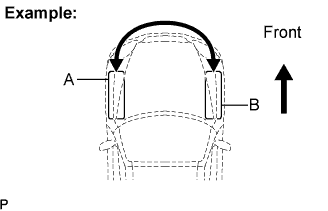 |
Interchange tire "A" with normal tire "B".
| NEXT | |
| 22.SET TIRE PRESSURE TO NORMAL VALUE |
Set the tire pressure of 4 wheels to the specified value.
| Tire Size | Front kPa (kgf/cm2, psi) | Rear kPa (kgf/cm2, psi) | ||
| For driving at speeds under 160 km/h (100 mph) | For driving at speeds of 160 km/h (100 mph) or over | For driving at speeds under 160 km/h (100 mph) | For driving at speeds of 160 km/h (100 mph) or over | |
| 245/40R 18 | 230 (2.3, 33) | 260 (2.6. 38) 270 (2.7, 39)* | 230 (2.3, 33) 260 (2.6. 38)* | 270 (2.7, 39) 310 (3.1, 45)* |
| 225/50R 17 | 230 (2.3, 33) | 260 (2.6. 38) 270 (2.7, 39)* | 230 (2.3, 33) 260 (2.6. 38)* | 270 (2.7, 39) 320 (3.2, 46)* |
| NEXT | |
| 23.PERFORM FORCED TRANSMISSION OF TRANSMITTER ID |
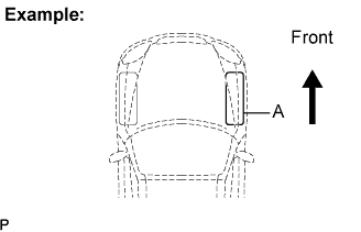 |
Remove the valve core of tire "A", rapidly reduce the tire pressure, and perform forced transmission of the transmitter ID of the tire pressure monitor valve sub-assembly.
| NEXT | |
| 24.CHECK DTC AGAIN |
Check for DTC.
|
| ||||
| OK | ||
| ||
