POWER DOOR LOCK CONTROL SYSTEM > Double Lock Function does not Operate Properly |

| 1.CHECK WIRELESS DOOR LOCK CONTROL SYSTEM |
Check that the doors can be locked and unlocked normally using the wireless operation.
|
| ||||
| OK | |
| 2.PERFORM ACTIVE TEST BY INTELLIGENT TESTER (DOUBLE DOOR LOCK MOTOR) |
Select the Active Test, use the intelligent tester to generate a control command, and then check that the double door lock motor operates normally.
| Item | Tester Details | Diagnostic Note |
| Double Lock Unset | Operate double lock motor/UNSET or SET | - |
|
| ||||
| OK | |
| 3.PERFORM ACTIVE TEST BY INTELLIGENT TESTER (DOUBLE DOOR LOCK MOTOR) |
Select the Active Test, use the intelligent tester to generate a control command, and then check that the double door lock motor operates normally.
| Item | Tester Details | Diagnostic Note |
| Double Lock Unset | Operate double lock motor/UNSET or SET | - |
|
| ||||
| OK | |
| 4.PERFORM ACTIVE TEST BY INTELLIGENT TESTER (DOUBLE DOOR LOCK MOTOR) |
Select the Active Test, use the intelligent tester to generate a control command, and then check that the double door lock motor operates normally.
| Item | Tester Details | Diagnostic Note |
| Double Lock Unset | Operate double lock motor/UNSET or SET | - |
|
| ||||
| OK | |
| 5.PERFORM ACTIVE TEST BY INTELLIGENT TESTER (DOUBLE DOOR LOCK MOTOR) |
Select the Active Test, use the intelligent tester to generate a control command, and then check that the double door lock motor operates normally.
| Item | Tester Details | Diagnostic Note |
| Double Lock Unset | Operate double lock motor/UNSET or SET | - |
|
| ||||
| OK | ||
| ||
| 6.INSPECT FRONT DOOR LOCK ASSEMBLY (DRIVER SIDE) (DOUBLE DOOR LOCK MOTOR) |
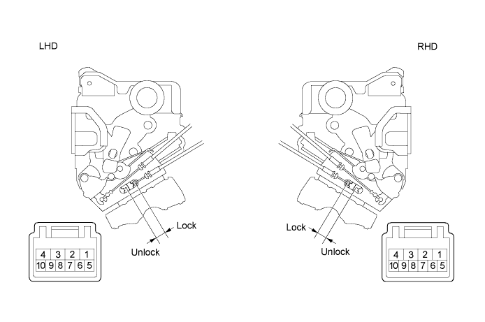
Check operation of the double lock motor.
Apply battery voltage to the door lock and set the door lock motor to the lock position.
| Measurement Condition | Specified Condition |
| Battery positive (+) → Terminal 4 Battery negative (-) → Terminal 3 | Lock |
| Battery positive (+) → Terminal 3 Battery negative (-) → Terminal 4 | Unlock |
| Measurement Condition | Specified Condition |
| Battery positive (+) → Terminal 2 Battery negative (-) → Terminal 1 | Lock |
| Battery positive (+) → Terminal 1 Battery negative (-) → Terminal 2 | Unlock |
Apply battery voltage to the door lock motor and check the operation of the double door lock motor.
| Measurement Condition | Specified Condition |
| Battery positive (+) → Terminal 2 Battery negative (-) → Terminal 1 | Set |
| Battery positive (+) → Terminal 1 Battery negative (-) → Terminal 2 | Unset |
| Measurement Condition | Specified Condition |
| Battery positive (+) → Terminal 4 Battery negative (-) → Terminal 3 | Set |
| Battery positive (+) → Terminal 3 Battery negative (-) → Terminal 4 | Unset |
While the double locking system is set, check that the doors cannot be unlocked by operating the control cable.
|
| ||||
| OK | |
| 7.READ VALUE OF INTELLIGENT TESTER (DOUBLE DOOR LOCK POSITION SWITCH) |
Check the Data List for proper functioning of the double door lock position switch.
| Item | Measurement Item/Display (Range) | Normal Condition | Diagnostic Note |
| Double Lock Position SW | Driver side double door lock position switch signal/ ON or OFF | ON: Driver side double door is unset OFF: Driver side double door is set | - |
|
| ||||
| NG | |
| 8.INSPECT FRONT DOOR LOCK ASSEMBLY (DRIVER SIDE) (DOUBLE DOOR LOCK POSITION SWITCH) |
Measure the resistance of the double door lock position switch.
| Tester Connection | Switch Condition | Specified Condition |
| 5 - 6 | Set | Below 1 Ω |
| 5 - 6 | Unset | 10 kΩ or higher |
| Tester Connection | Switch Condition | Specified Condition |
| 9 - 10 | Set | Below 1 Ω |
| 9 - 10 | Unset | 10 kΩ or higher |
|
| ||||
| OK | |
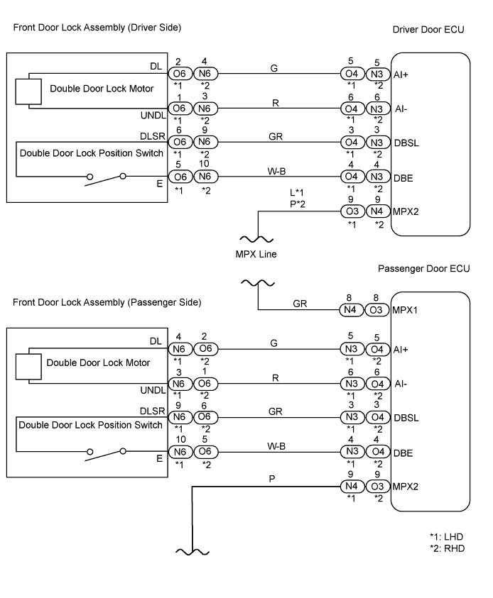
| 9.CHECK WIRE HARNESS (DRIVER DOOR ECU - FRONT DOOR LOCK ASSEMBLY (DRIVER SIDE)) |
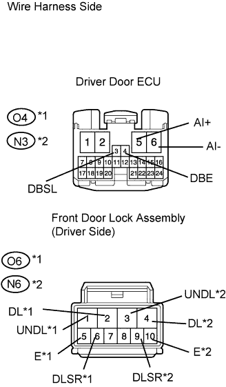 |
Disconnect the O4*1 or N3*2 ECU connector.
Disconnect the O6*1 or N6*2 door lock connector.
Measure the resistance of the wire harness side connectors.
| Tester Connection | Specified Condition |
| O4-5 (AI+) - O6-2 (DL) | Below 1 Ω |
| O4-6 (AI-) - O6-1 (UNDL) | Below 1 Ω |
| O4-3 (DBSL) - O6-6 (DLSR) | Below 1 Ω |
| O4-4 (DBE) - O6-5 (E) | Below 1 Ω |
| Tester Connection | Specified Condition |
| N3-5 (AI+) - N6-4 (DL) | Below 1 Ω |
| N3-6 (AI-) - N6-3 (UNDL) | Below 1 Ω |
| N3-3 (DBSL) - N6-9 (DLSR) | Below 1 Ω |
| N3-4 (DBE) - N6-10 (E) | Below 1 Ω |
|
| ||||
| OK | ||
| ||
| 10.INSPECT FRONT DOOR LOCK ASSEMBLY (PASSENGER SIDE) (DOUBLE DOOR LOCK MOTOR) |

Check operation of the double lock motor.
Apply battery voltage to the door lock and set the door lock motor to the lock position.
| Measurement Condition | Specified Condition |
| Battery positive (+) → Terminal 2 Battery negative (-) → Terminal 1 | Lock |
| Battery positive (+) → Terminal 1 Battery negative (-) → Terminal 2 | Unlock |
| Measurement Condition | Specified Condition |
| Battery positive (+) → Terminal 4 Battery negative (-) → Terminal 3 | Lock |
| Battery positive (+) → Terminal 3 Battery negative (-) → Terminal 4 | Unlock |
Apply battery voltage to the door lock motor and check the operation of the double door lock motor.
| Measurement Condition | Specified Condition |
| Battery positive (+) → Terminal 4 Battery negative (-) → Terminal 3 | Set |
| Battery positive (+) → Terminal 3 Battery negative (-) → Terminal 4 | Unset |
| Measurement Condition | Specified Condition |
| Battery positive (+) → Terminal 2 Battery negative (-) → Terminal 1 | Set |
| Battery positive (+) → Terminal 1 Battery negative (-) → Terminal 2 | Unset |
While the double locking system is set, check that the doors cannot be unlocked by operating the control cable.
|
| ||||
| OK | |
| 11.READ VALUE OF INTELLIGENT TESTER (DOUBLE DOOR LOCK POSITION SWITCH) |
Check the Data List for proper functioning the of double door lock position switch.
| Item | Measurement Item/Display (Range) | Normal Condition | Diagnostic Note |
| Double Lock Position SW | Passenger side double door lock position switch signal/ ON or OFF | ON: Passenger side double door is unset OFF: Passenger side double door is set | - |
|
| ||||
| NG | |
| 12.INSPECT FRONT DOOR LOCK ASSEMBLY (PASSENGER SIDE) (DOUBLE DOOR LOCK POSITION SWITCH) |
Measure the resistance of the double door lock position switch.
| Tester Connection | Switch Condition | Specified Condition |
| 9 - 10 | Set | Below 1 Ω |
| 9 - 10 | Unset | 10 kΩ or higher |
| Tester Connection | Switch Condition | Specified Condition |
| 5 - 6 | Set | Below 1 Ω |
| 5 - 6 | Unset | 10 kΩ or higher |
|
| ||||
| OK | |
| 13.CHECK WIRE HARNESS (PASSENGER DOOR ECU - FRONT DOOR LOCK ASSEMBLY) |
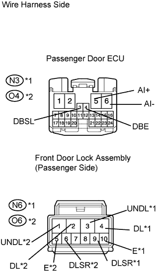 |
Disconnect the N3*1 or O4*2 ECU connector.
Disconnect the N6*1 or O6*2 door lock connector.
Measure the resistance of the wire harness side connectors.
| Tester Connection | Specified Condition |
| N3-5 (AI+) - N6-4 (DL) | Below 1 Ω |
| N3-6 (AI-) - N6-3 (UNDL) | Below 1 Ω |
| N3-3 (DBSL) - N6-9 (DLSR) | Below 1 Ω |
| N3-4 (DBE) - N6-10 (E) | Below 1 Ω |
| Tester Connection | Specified Condition |
| O4-5 (AI+) - O6-2 (DL) | Below 1 Ω |
| O4-6 (AI-) - O6-1 (UNDL) | Below 1 Ω |
| O4-3 (DBSL) - O6-6 (DLSR) | Below 1 Ω |
| O4-4 (DBE) - O6-5 (E) | Below 1 Ω |
|
| ||||
| OK | ||
| ||
| 14.INSPECT REAR DOOR LOCK ASSEMBLY LH (DOUBLE DOOR LOCK MOTOR) |
 |
Check operation of the double lock motor.
Apply battery voltage to the door lock and set the door lock motor to the lock position.
| Measurement Condition | Specified Condition |
| Battery positive (+) → Terminal 4 Battery negative (-) → Terminal 1 | Lock |
| Battery positive (+) → Terminal 1 Battery negative (-) → Terminal 4 | Unlock |
Apply battery voltage to the door lock motor and check the operation of the double door lock motor.
| Measurement Condition | Specified Condition |
| Battery positive (+) → Terminal 4 Battery negative (-) → Terminal 3 | Set |
| Battery positive (+) → Terminal 3 Battery negative (-) → Terminal 4 | Unset |
While the double locking system is set, check that the doors cannot be unlocked by operating the control cable.
|
| ||||
| OK | |
| 15.READ VALUE OF INTELLIGENT TESTER (DOUBLE DOOR LOCK POSITION SWITCH) |
Check the Data List for proper functioning the of double door lock position switch.
| Item | Measurement Item/Display (Range) | Normal Condition | Diagnostic Note |
| Double Lock Position SW | Rear LH side double door lock position switch signal/ ON or OFF | ON: Rear LH side double door is unset OFF: Rear LH side double door is set | - |
|
| ||||
| NG | |
| 16.INSPECT REAR DOOR LOCK ASSEMBLY LH (DOUBLE DOOR LOCK POSITION SWITCH) |
|
Measure the resistance of the double door lock position switch.
| Tester Connection | Switch Condition | Specified Condition |
| 9 - 10 | Set | Below 1 Ω |
| 9 - 10 | Unset | 10 kΩ or higher |
|
| ||||
| OK | |
| 17.CHECK WIRE HARNESS (REAR DOOR LH ECU - REAR DOOR LOCK ASSEMBLY LH) |
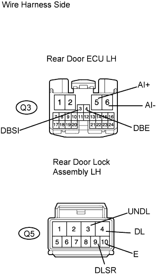 |
Disconnect the Q3 ECU connector.
Disconnect the Q5 door lock connector.
Measure the resistance of the wire harness side connectors.
| Tester Connection | Specified Condition |
| Q3-5 (AI+) - Q5-4 (DL) | Below 1 Ω |
| Q3-6 (AI-) - Q5-3 (UNDL) | Below 1 Ω |
| Q3-3 (DBSI) - Q5-9 (DLSR) | Below 1 Ω |
| Q3-4 (DBE) - Q5-10 (E) | Below 1 Ω |
|
| ||||
| OK | ||
| ||
| 18.INSPECT REAR DOOR LOCK ASSEMBLY RH (DOUBLE DOOR LOCK MOTOR) |
 |
Check operation of the double lock motor.
Apply battery voltage to the door lock and set the door lock motor to the lock position.
| Measurement Condition | Specified Condition |
| Battery positive (+) → Terminal 4 Battery negative (-) → Terminal 3 | Lock |
| Battery positive (+) → Terminal 3 Battery negative (-) → Terminal 4 | Unlock |
Apply battery voltage to the door lock motor and check the operation of the double door lock motor.
| Measurement Condition | Specified Condition |
| Battery positive (+) → Terminal 2 Battery negative (-) → Terminal 1 | Set |
| Battery positive (+) → Terminal 1 Battery negative (-) → Terminal 2 | Unset |
While the double locking system is set, check that the doors cannot be unlocked by operating the control cable.
|
| ||||
| OK | |
| 19.READ VALUE OF INTELLIGENT TESTER (DOUBLE DOOR LOCK POSITION SWITCH) |
Check the Data List for proper functioning the of double door lock position switch.
| Item | Measurement Item/Display (Range) | Normal Condition | Diagnostic Note |
| Double Lock Position SW | Rear RH side double door lock position switch signal/ ON or OFF | ON: Rear RH side double door is unset OFF: Rear RH side double door is set | - |
|
| ||||
| NG | |
| 20.INSPECT REAR DOOR LOCK ASSEMBLY RH (DOUBLE DOOR LOCK POSITION SWITCH) |
|
Measure the resistance of the double door lock position switch.
| Tester Connection | Switch Condition | Specified Condition |
| 5 - 6 | Set | Below 1 Ω |
| 5 - 6 | Unset | 10 kΩ or higher |
|
| ||||
| OK | |
| 21.CHECK WIRE HARNESS (REAR DOOR RH ECU - REAR DOOR LOCK ASSEMBLY RH) |
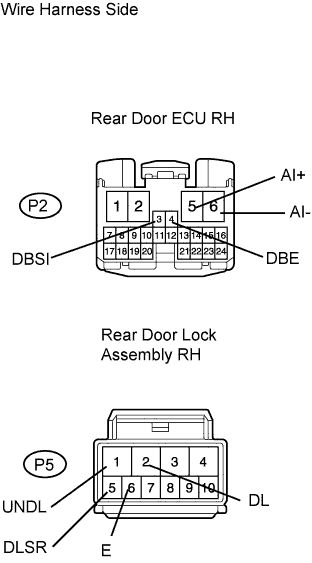 |
Disconnect the P2 ECU connector.
Disconnect the P5 door lock connector.
Measure the resistance of the wire harness side connectors.
| Tester Connection | Specified Condition |
| P2-5 (AI+) - P5-2 (DL) | Below 1 Ω |
| P2-6 (AI-) - P5-1 (UNDL) | Below 1 Ω |
| P2-3 (DBSI) - P5-5 (DLSR) | Below 1 Ω |
| P2-4 (DBE) - P5-6 (E) | Below 1 Ω |
|
| ||||
| OK | ||
| ||
