DTC    P0516    Battery Temperature Sensor Circuit Low

DTC    P0517    Battery Temperature Sensor Circuit High

for Preparation Click here


DESCRIPTION

A110648E01
The battery thermometer sensor installed on the battery cover detects battery temperature.
A thermistor is integrated into the battery thermometer sensor, and the resistance in the battery thermometer sensor changes according to the battery temperature.
The resistance of the thermistor in the battery thermometer sensor decreases as the battery temperature increases. The resistance increases as the temperature decreases.
The battery thermometer sensor is connected to the ECM. The ECM supplies 5 V from the THB terminal to the battery thermometer sensor through resistor R.
The battery thermometer sensor and resistor R are connected in series. This results in fluctuations in the voltage supplied from the THB terminal when the resistance changes according to the battery temperature.
The ECM determines the battery temperature according to fluctuations in voltage. When the battery temperature is high, the ECM determines to reduce the amount of current supplied from the generator in order to protect the battery.

DTC No.
DTC Detection Condition
Trouble Area
P0516
Battery thermometer sensor output value is 0.2 V or less for 0.5 seconds or more with the engine switch on (IG)
(1 trip detection logic)
  1. Battery thermometer sensor
  2. Short in battery thermometer sensor circuit
  3. ECM
P0517
Battery thermometer sensor output value is 4.8 V or more for 0.5 seconds or more with the engine switch on (IG)
(1 trip detection logic)
  1. Battery thermometer sensor
  2. Open in battery thermometer sensor circuit
  3. ECM

WIRING DIAGRAM


A110643E01


INSPECTION PROCEDURE

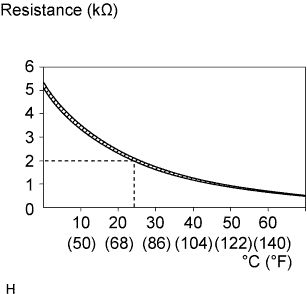
1.INSPECT BATTERY THERMOMETER SENSOR
A080940E01
  1. Disconnect the A47 battery thermometer sensor connector.

  1. Measure the resistance of the battery thermometer sensor.

    Standard resistance:
    1.91 to 2.065 kΩ at 24 to 26°C


NG
REPLACE BATTERY THERMOMETER SENSOR
OK


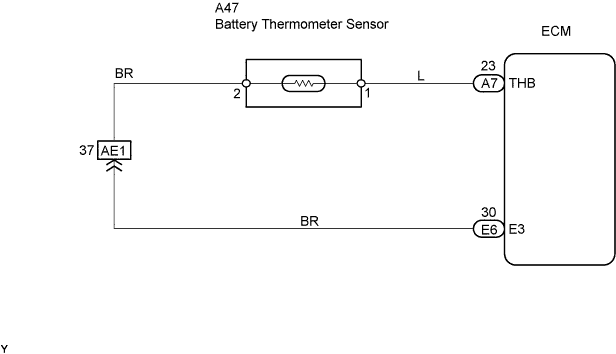
2.CHECK HARNESS AND CONNECTOR (BATTERY THERMOMETER SENSOR - ECM)
A110649E01
  1. Check the harness and the connectors between the ECM and the battery thermometer sensor.

    1. Disconnect the A47 battery thermometer sensor connector.

    2. Disconnect the E6 and A7 ECM connectors.

    3. Measure the resistance of the wire harness side connectors.

      Standard resistance (Check for open):
      Tester Connection
      Specified Condition
      A47-1 - THB (A7-23)
      Below 1 Ω
      A47-2 - E3 (E6-30)
      Below 1 Ω

      Standard resistance (Check for short):
      Tester Connection
      Specified Condition
      A47-1 or THB (A7-23) - Body ground
      10 kΩ or higher
      A47-2 or E3 (E6-30) - Body ground
      10 kΩ or higher


NG
REPAIR OR REPLACE HARNESS AND CONNECTOR
OK

REPLACE ECM