BRAKE PEDAL STROKE SENSOR > INSTALLATION |
| 1. INSTALL BRAKE PEDAL STROKE SENSOR ASSEMBLY |
New brake pedal stroke sensor assembly:
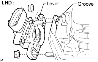
Install a new brake pedal stroke sensor assembly with the 2 nuts. (for LHD)
Install a new brake pedal stroke sensor assembly with the 2 bolts. (for RHD)
Strongly depress the brake pedal and break the brake pedal stroke sensor assembly lever set pin.
Remove the broken lever set pin.
Connect the brake pedal stroke sensor assembly connector.
Reuse of brake pedal stroke sensor assembly:
 |
Temporarily install the brake pedal stroke sensor assembly with the 2 nuts. (for LHD)
 |
Temporarily install the brake pedal stroke sensor assembly with the 2 bolts. (for RHD)
Connect the connector of the brake pedal stroke sensor assembly.
Connect the cable to the negative battery terminal.
Connect the intelligent tester to the DLC3.
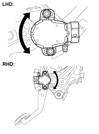 |
Turn the engine switch on (IG). Reading the value of the stroke sensor 1 shown on the data monitor, turn the stroke sensor slowly to the right and left to adjust it to the standard voltage.
Fully tighten the 2 nuts. (for LHD)
Fully tighten the 2 bolts. (for RHD)
| 2. INSTALL DRIVER SIDE KNEE AIRBAG ASSEMBLY |
 |
Connect the connector.
Install the driver side knee airbag assembly with the 4 bolts.
| 3. INSTALL INSTRUMENT PANEL NO.1 SAFETY PAD SUB-ASSEMBLY |
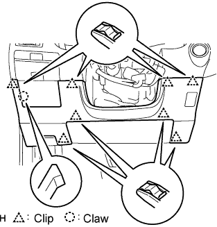 |
Install the hood lock control cable to the safety pad.
Attach the 8 clips and claw to install the safety pad.
| 4. INSTALL INSTRUMENT PANEL NO.1 UNDER COVER SUB-ASSEMBLY |
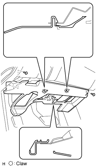 |
Connect the connectors.
Attach the 2 claws to install the under cover.
Install the 2 screws.
| 5. INSTALL INSTRUMENT SIDE PANEL LH (for LHD) |
 |
Attach the 2 claws and 4 clips to install the side panel.
| 6. INSTALL INSTRUMENT SIDE PANEL RH (for RHD) |
 |
Attach the 2 claws and 4 clips to install the side panel.
| 7. INSTALL FRONT DOOR OPENING TRIM COVER LH (for LHD) |
Attach the 3 claws to install the trim cover.
Pull out the folded lip of the weatherstrip.
| 8. INSTALL FRONT DOOR OPENING TRIM COVER RH (for RHD) |
| 9. INSTALL FRONT DOOR SCUFF PLATE LH (for LHD) |
 |
Attach the 5 claws to install the scuff plate.
Pull out the folded lip of the weatherstrip.
| 10. INSTALL FRONT DOOR SCUFF PLATE RH (for RHD) |
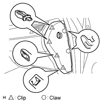
| 11. INSTALL INSTRUMENT PANEL FINISH PANEL END LH (for LHD) |
 |
Attach the 4 clips and 3 claws to install the finish panel end.
Install the screw.
| 12. INSTALL INSTRUMENT PANEL FINISH PANEL END RH (for RHD) |
 |
Attach the 3 clips and 3 claws to install the finish panel end.
Install the screw.
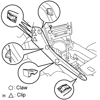
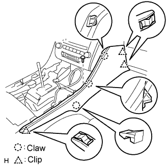
| 13. INSTALL CONSOLE UPPER PANEL SUB-ASSEMBLY |
 |
Connect the connector.
Attach the 9 clips to install the ash receptacle.
 |
Install the shift lever knob and twist it in the direction indicated by the arrow.
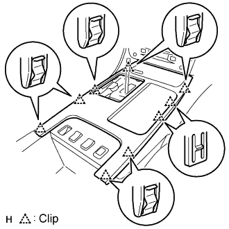
| 14. INSTALL CONSOLE UPPER PANEL GARNISH |
Attach the claws to install the garnish.
| 15. INSPECT SRS WARNING LIGHT |
| 16. CHECK AND CLEAR DTC |
| 17. PERFORM INITIALIZATION |
