BRAKE PEDAL STROKE SENSOR > REMOVAL |
| 1. DISCONNECT CABLE FROM NEGATIVE BATTERY TERMINAL |
| 2. REMOVE CONSOLE UPPER PANEL GARNISH |
 |
Using a clip remover, detach the claws and remove the garnish.
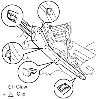
| 3. REMOVE CONSOLE UPPER PANEL SUB-ASSEMBLY |
 |
Twist the shift lever knob in the direction indicated by the arrow and remove it.
 |
Using a screwdriver, detach the 9 clips.
Remove the ash receptacle and then disconnect the connector.
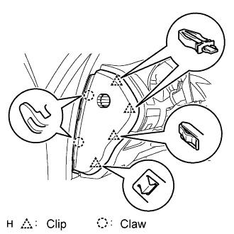
| 4. REMOVE INSTRUMENT PANEL FINISH PANEL END LH (for LHD) |
 |
Remove the screw.
Using a screwdriver, detach the 4 clips and 3 claws.
Remove the finish panel end.
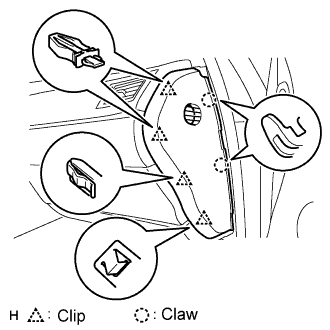
| 5. REMOVE INSTRUMENT PANEL FINISH PANEL END RH (for RHD) |
 |
Remove the screw.
Using a screwdriver, detach the 3 clips and 3 claws.
Remove the finish panel end.
| 6. REMOVE FRONT DOOR SCUFF PLATE LH (for LHD) |
 |
Using a moulding remover, detach the 5 claws and remove the scuff plate.
| 7. REMOVE FRONT DOOR SCUFF PLATE RH (for RHD) |
| 8. REMOVE FRONT DOOR OPENING TRIM COVER LH (for LHD) |
Using a moulding remover, detach the 3 claws and remove the trim cover.
| 9. REMOVE FRONT DOOR OPENING TRIM COVER RH (for RHD) |
| 10. REMOVE INSTRUMENT SIDE PANEL LH (for LHD) |
 |
Using a screwdriver, detach the 2 claws and 4 clips, and remove the side panel.
| 11. REMOVE INSTRUMENT SIDE PANEL RH (for RHD) |
 |
Using a screwdriver, detach the 2 claws and 4 clips, and remove the side panel.
| 12. REMOVE INSTRUMENT PANEL NO.1 UNDER COVER SUB-ASSEMBLY |
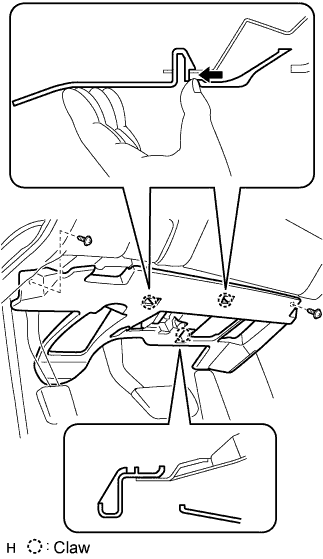 |
Remove the 2 screws.
Detach the 2 claws.
Remove the under cover and then disconnect the connector.
| 13. REMOVE INSTRUMENT PANEL NO.1 SAFETY PAD SUB-ASSEMBLY |
 |
Using a screwdriver, detach the 8 clips and claw.
Remove the hood lock control cable from the safety pad.
Remove the safety pad.
| 14. REMOVE DRIVER SIDE KNEE AIRBAG ASSEMBLY |
 |
Remove the 4 bolts and driver side knee airbag assembly.
Disconnect the connector.
| 15. REMOVE BRAKE PEDAL STROKE SENSOR ASSEMBLY |
Disconnect the brake pedal stroke sensor assembly connector.
 |
Remove the 2 nuts and the brake pedal stroke sensor assembly. (for LHD)
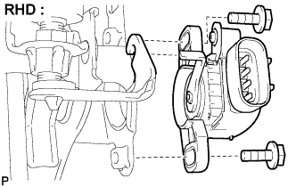 |
Remove the 2 bolts and the brake pedal stroke sensor assembly. (for RHD)
