THEFT DETERRENT SYSTEM > Theft Warning Siren Circuit |
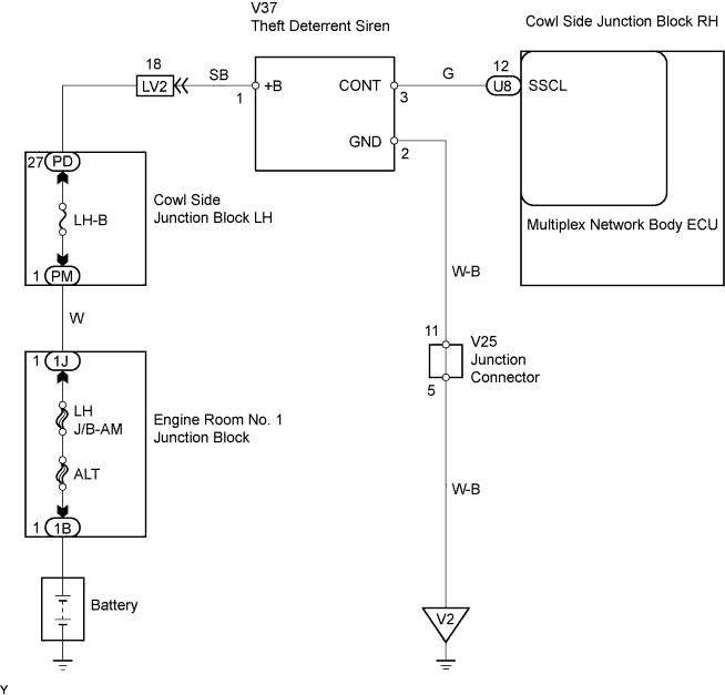
| 1.CHECK THEFT WARNING SIREN |
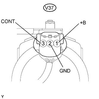 |
Measure the voltage of the connector.
| Tester Connection | Condition | Specified Condition |
| V37-1 (+B) - Body ground | Always | 10 to 14 V |
| V37-2 (GND) - Body ground | Always | Below 1 V |
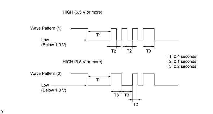
| V37-3 (CONT) - Body ground | When switched from armed state or arming preparation state to disarmed state (1) | Wave pattern (1) shown in chart below |
| When switched from arming preparation state to armed state (2) | Wave pattern (2) shown in chart below | |
| Normal condition (Except (1) and (2)) | Approx. 1.4 V |
Wave pattern
|
| ||||
| OK | |
| 2.CHECK WIRE HARNESS (MULTIPLEX NETWORK BODY ECU - THEFT WARNING SIREN) |
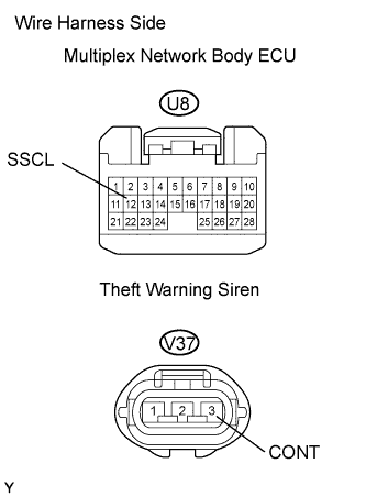 |
Disconnect the U8 ECU connector.
Disconnect the V37 siren connector.
Check the resistance between the wire harness side connectors.
| Tester Connection | Specified Condition |
| U8-12 (SSCL) - V37-3 (CONT) | Below 1 Ω |
|
| ||||
| OK | |
| 3.CHECK WIRE HARNESS (THEFT WARNING SIREN - BODY GROUND) |
 |
Disconnect the V37 siren connector.
Check the resistance between the wire harness side connector.
| Tester Connection | Specified Condition |
| V37-2 (GND) - Body ground | Below 1 Ω |
|
| ||||
| OK | ||
| ||
