SKID CONTROL ECU > INSTALLATION |
| 1. INSTALL SKID CONTROL ECU ASSEMBLY |
 |
Connect the 3 connectors and press the lock levers down to lock the connectors.
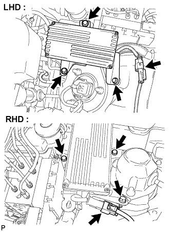 |
Install the skid control ECU assembly with the 3 bolts.
Connect the connector.
| 2. INSTALL ENGINE ROOM SIDE COVER RH (for RHD) |
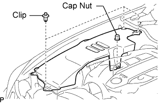 |
Install the side cover with the 3 clips and cap nut.
| 3. INSTALL ENGINE ROOM SIDE COVER LH (for LHD) |
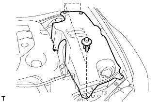 |
Install the side cover with the 3 clips.
| 4. INSTALL COOL AIR INTAKE DUCT SEAL |
 |
Install the intake duct seal with the 7 clips.
| 5. CONNECT CABLE TO NEGATIVE BATTERY TERMINAL |
| 6. CHECK AND CLEAR DTC |
| 7. PREFORM ZERO POINT CALIBRATION OF YAW RATE SENSOR |
| 8. PERFORM LINEAR VALVE OFFSET LEARNING |
| 9. PERFORM INITIALIZATION |
