BRAKE ACTUATOR (w/ VSC) > INSTALLATION |
| 1. INSTALL ABS AND TRACTION ACTUATOR ASSEMBLY WITH BRACKET |
Install the actuator assembly with bracket to the body with the 2 bolts and nut.

 |
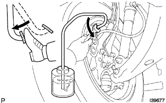
Using SST, connect the brake No.3 tube to the flexible hose. (for LHD)
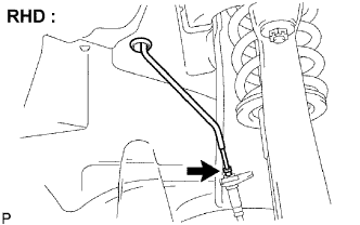 |
Using SST, connect the brake No.2 tube to the flexible hose. (for RHD)
Install the grommet to the body.
Temporarily tighten each brake tube to the connect positions of the actuator assembly with bracket as shown in the illustration.

 |
Using SST, fully tighten each brake tube to the correct positions of the actuator assembly with bracket as shown in the illustration.
Connect the actuator connector.
| 2. INSTALL BRAKE MASTER WITH PLATE CYLINDER SUB-ASSEMBLY |
Install a new O-ring to the brake master cylinder sub-assembly.
 |
Install the brake master cylinder sub-assembly to the booster assembly with the 2 nuts.
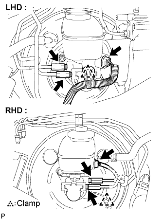 |
Using SST, connect the 2 brake tubes to the brake master cylinder sub-assembly.
Engage the clamp and connect the warning switch connector.
| 3. INSTALL ENGINE ROOM RELAY NO.3 BLOCK |
 |
Install the relay block No.3 with the bolt and nut.
| 4. FILL RESERVOIR WITH BRAKE FLUID |
 |
Fill reservoir with brake fluid.
| 5. BLEED BRAKE MASTER CYLINDER SUB-ASSEMBLY |
Disconnect the 2 brake lines from the master cylinder.
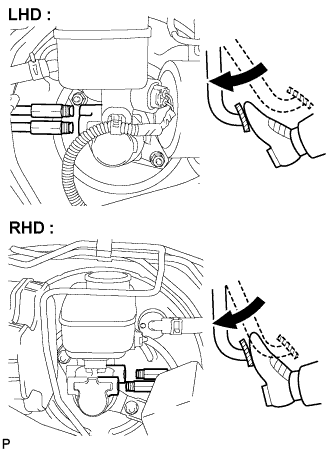 |
Slowly depress the brake pedal and hold it.
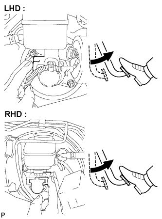 |
Cover the 2 outer holes with fingers, and release the brake pedal.
Repeat (b) and (c) 3 or 4 times.
Using SST, connect the brake lines to the master cylinder.
| 6. CONNECT CABLE TO NEGATIVE BATTERY TERMINAL |
| 7. BLEED BRAKE LINE |
Connect a vinyl tube to the bleeder plug.
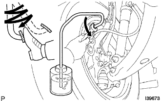 |
Depress the brake pedal several times, then loosen the bleeder plug with the pedal depressed.
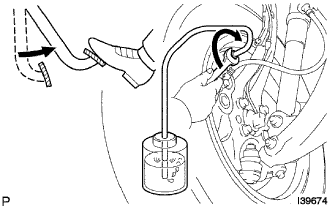 |
When fluid stops coming out, tighten the bleeder plug, then release the brake pedal.
Repeat (b) and (c) until all the air in the fluid is completely bled out.
Using SST, tighten the bleeder plug completely.
Repeat the above procedures for each wheel to bleed the air from the brake line.
| 8. INSTALL FRONT WHEEL |
| 9. INSPECT DTC |
| 10. BLEED ABS AND TRACTION ACTUATOR ASSEMBLY |
Depress the brake pedal more than 20 times with the engine switch off.
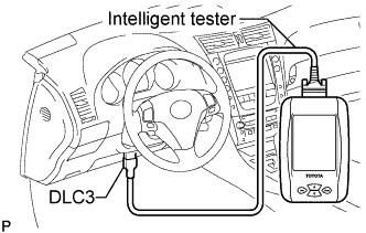 |
Connect the intelligent tester to the DLC3, then turn the engine switch on (IG).
Turn the intelligent tester on and select "AIR BLEEDING" on the screen.
Bleed the air according to "Step 1: Increase" on the intelligent tester display.
|
Connect a vinyl tube to either one of the bleeder plugs.
Depress the brake pedal several times, then loosen the bleeder plug connected to the vinyl tube with the pedal depressed.
|
When fluid stops coming out, tighten the bleeder plug, then release the brake pedal.
Repeat (2) and (3) until all the air in the fluid is completely bled out.
Using SST, tighten the bleeder plug completely.
Repeat the above procedures for the rest of the wheels to bleed the air from the brake line.
Bleed the air from the suction line according to "Step 2: Inhalation" on the intelligent tester display.
 |
Connect a vinyl tube to the bleeder plug at the right front wheel or the right rear wheel and loosen the bleeder plug.
Operate the ABS and TRACTION actuator assembly to bleed the air using the intelligent tester.
Check that the operation has stopped by referring to the intelligent tester display and tighten the bleeder plug.
Repeat (2) and (3) until all the air in the fluid is completely bled out.
Using SST, tighten the bleeder plug completely.
For the rest of the wheels, bleed the air in the same way as stated in the above procedures.
Bleed the air from the pressure reduction line according to "Step 3: Decrease" on the intelligent tester display.
Connect a vinyl tube to either one of the bleeder plugs.
Loosen the bleeder plug.
 |
Using the intelligent tester, operate the ABS and TRACTION actuator assembly, completely depress the brake pedal and hold it.
Tighten the bleeder plug, then release the brake pedal.
Repeat (2) to (4) until all the air in the fluid is completely bled out.
Using SST, tighten the bleeder plug completely.
Repeat the above procedures for the rest of the brakes to bleed the air from the brake line.
Bleed the air from the brake line again according to "Step 4: Increase" on the intelligent tester display.
Connect a vinyl tube to either one of the bleeder plugs.
|
Depress the brake pedal several times, then loosen the bleeder plug connected to the vinyl tube with the pedal depressed.
|
When fluid stops coming out, tighten the bleeder plug, then release the brake pedal.
Repeat (2) and (3) until all the air in the fluid is completely bled out.
Using SST, tighten the bleeder plug completely.
Repeat the above procedures for each brake to bleed the air from the brake line.
Finish "AIR BLEEDING" on the intelligent tester and turn off the power.
Disconnect the intelligent tester from the DLC3.
Turn the engine switch off.
| 11. CHECK FLUID LEVEL IN RESERVOIR |
Check the fluid level and add fluid if necessary.
| 12. INSPECT BRAKE FLUID LEAKAGE |
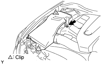
| 13. INSTALL COWL TOP VENTILATOR LOUVER SUB-ASSEMBLY |
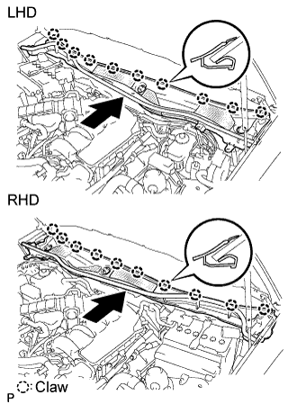 |
Push the ventilator louver in the direction indicated by the arrow in the illustration. Attach the 10 claws to install the ventilator louver.
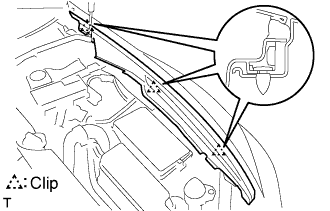
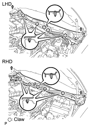 |
Attach the 5 claws and 2 clips to install the ventilator louver.
| 14. INSTALL FRONT FENDER TO COWL SIDE SEAL LH |
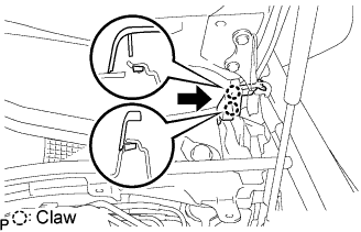 |
Push the cowl side seal in the direction indicated by the arrow in the illustration. Attach the 2 claws to install the cowl side seal.
| 15. INSTALL FRONT FENDER TO COWL SIDE SEAL RH |
| 16. INSTALL FRONT WIPER ARM AND BLADE ASSEMBLY LH |
 |
Stop the wiper motor at the automatic stop position.
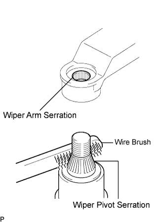
Clean the wiper arm serration with a round file or equivalent.
Clean the wiper pivot serration with a wire brush.
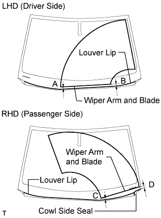 |
Install the wiper arm and blade with the nut. Make sure that the wiper arm and blade comes to the position shown in the illustration.
| Area | Measurement |
| A (for LHD) | 25.3 mm (0.996 in.) |
| B (for LHD) | 26.2 mm (1.031 in.) |
| C (for RHD) | 21.8 mm (0.858 in.) |
| D (for RHD) | 28.9 mm (1.138 in.) |
| 17. INSTALL FRONT WIPER ARM AND BLADE ASSEMBLY RH |
|
Stop the wiper motor at the automatic stop position.
Clean the wiper arm serration with a round file or equivalent.
Clean the wiper pivot serration with a wire brush.
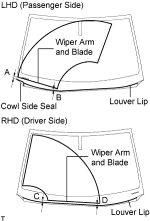 |
Install the wiper arm and blade with the nut. Make sure that the wiper arm and blade comes to the position shown in the illustration.
| Area | Measurement |
| A (for LHD) | 28.9 mm (1.138 in.) |
| B (for LHD) | 21.8 mm (0.858 in.) |
| C (for RHD) | 26.2 mm (1.031 in.) |
| D (for RHD) | 25.3 mm (0.996 in.) |
Operate the front wipers while spraying washer fluid on the windshield glass. Make sure that the front wipers function properly and there is no interference with the vehicle body.
| 18. INSTALL ENGINE ROOM SIDE COVER LH |
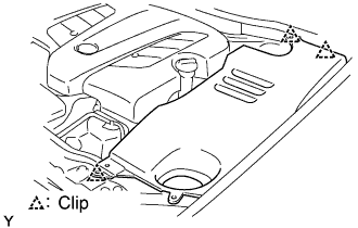 |
Install the side cover with the 3 clips.
| 19. INSTALL ENGINE ROOM SIDE COVER RH |
 |
Install the side cover with the 2 clips and nut.
| 20. INSTALL FRONT PILLAR TO FRONT SIDE SEAL SUB-ASSEMBLY RH |
 |
Attach the 3 clips to install the side seal.
| 21. INSTALL FRONT PILLAR TO FRONT SIDE SEAL SUB-ASSEMBLY LH |
| 22. INSTALL COOL AIR INTAKE DUCT SEAL |
 |
Install the intake duct seal with the 7 clips.
| 23. PERFORM YAW RATE SENSOR ZERO POINT CALIBRATION |
| 24. INSPECT VSC SENSOR SIGNAL |
| 25. INSPECT ACTUATOR WITH INTELLIGENT TESTER |
| 26. PERFORM INITIALIZATION |
