BRAKE ACTUATOR (w/ ECB) > REMOVAL |
| 1. DISCONNECT CABLE FROM NEGATIVE BATTERY TERMINAL |
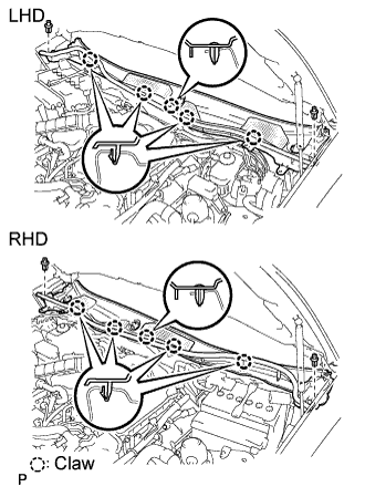
| 2. REMOVE COOL AIR INTAKE DUCT SEAL |
 |
Remove the 7 clips and duct seal.
| 3. REMOVE ENGINE ROOM SIDE COVER RH |
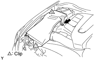 |
Remove the nut, 2 clips and side cover.
| 4. REMOVE ENGINE ROOM SIDE COVER LH |
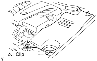 |
Remove the 3 clips and side cover.
| 5. REMOVE FRONT PILLAR TO FRONT SIDE SEAL SUB-ASSEMBLY LH |
 |
Using a clip remover, detach the 3 clips and remove the side seal.
| 6. REMOVE FRONT PILLAR TO FRONT SIDE SEAL SUB-ASSEMBLY RH |
| 7. REMOVE FRONT WIPER ARM AND BLADE ASSEMBLY LH |
Remove the nut, wiper arm and blade.
| 8. REMOVE FRONT WIPER ARM AND BLADE ASSEMBLY RH |
| 9. REMOVE FRONT FENDER TO COWL SIDE SEAL LH |
 |
Pull the cowl side seal in the direction indicated by the arrow in the illustration to detach the 2 claws and remove the cowl side seal.
| 10. REMOVE FRONT FENDER TO COWL SIDE SEAL RH |
| 11. REMOVE COWL TOP VENTILATOR LOUVER SUB-ASSEMBLY |
 |
Remove the 2 clips and detach the 5 claws.
 |
Pull the ventilator louver in the direction indicated by the arrow in the illustration to detach the 10 claws and remove the ventilator louver.
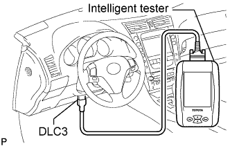
| 12. PERFORM ACCUMULATOR PRESSURE ZERO DOWN |
Connect the intelligent tester to the DLC3 with the engine switch off.
Turn the intelligent tester on and repeat the following steps 5 times.
Turn the engine switch on (IG).
Turn the intelligent tester on and select "DIAGNOSTIC MENU" → "ABS/VSC" → "ECB UTILITY" → "ZERO DOWN" on the intelligent tester.
When the buzzer sounds, turn the engine switch off.
| 13. DISABLE BRAKE CONTROL |
Move the shift lever to the P position and apply the parking brake.
 |
Connect the intelligent tester to the DLC3 with the engine switch off.
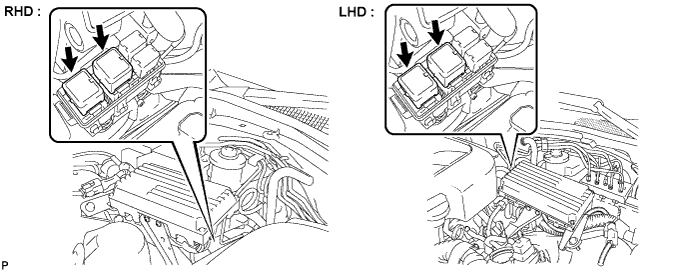
Remove the 2 ABS motor relays with the engine switch off from the engine room relay block No.3.
Turn the engine switch on (IG).
Turn the intelligent tester on and select "DIAGNOSTIC MENU"→"ABS/VSC"→"ECB UTILITY"→"ECB INVALID".
| 14. DRAIN BRAKE FLUID |
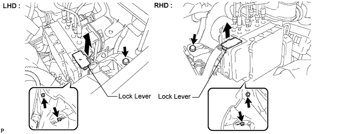
| 15. REMOVE SKID CONTROL ECU ASSEMBLY |
Disconnect the connector.
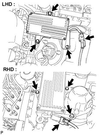 |
Remove the 3 bolts and skid control ECU assembly.
 |
Pull the 2 lock levers upward to release the lock and disconnect the 3 connectors.
| 16. SEPARATE ENGINE ROOM RELAY NO.3 BLOCK |
Separate the engine room relay No.3 block.
| 17. REMOVE FRONT WHEEL LH |
| 18. REMOVE BRAKE ACTUATOR ASSEMBLY WITH ACTUATOR BRACKET |
 |
Using SST, disconnect the brake tubes from the actuator assembly with bracket.
Remove the clip and reservoir tube No.1 hose.
Use tags or make a memo to identify the places to reconnect.

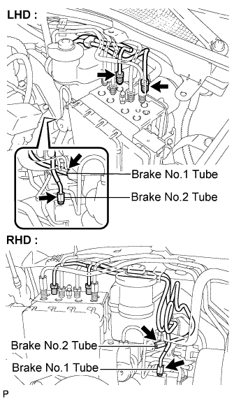 |
Using SST, disconnect the brake No.1 and No.2 tubes.
Release the lock lever and disconnect the actuator connector.
Remove the 2 bolts, nut and brake actuator assembly with bracket.