INSTALLATION
Removal / installation
| 1. INSTALL RADIATOR ASSEMBLY |

Install the 2 radiator support cushions and the 2 lower radiator supports to the radiator assembly.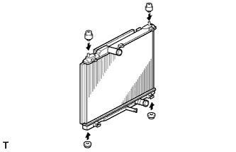

Install the cooling fan assembly to the radiator assembly by engaging them at the bottom. Engage the 3 claws to secure the cooling fan assembly to the radiator assembly.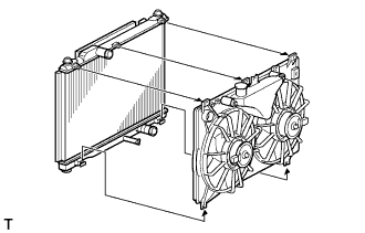
Install the radiator assembly to the vehicle together with the cooling fan assembly.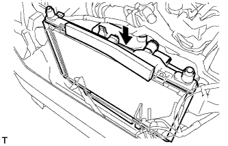
- NOTICE:
- Make sure that the cooler condenser assembly and radiator assembly do not come into contact with each other.
| 2. INSTALL RESERVE TANK CAP SUB-ASSEMBLY |
Install the reserve tank cap sub-assembly to the reserve tank.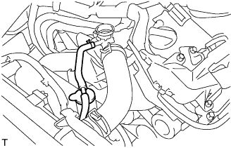
| 3. INSTALL ENGINE ROOM ECU OUTLET DUCT |
Install the engine room ECU outlet duct to the engine room ECU box.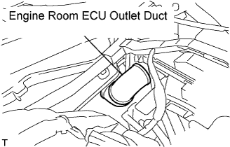
| 4. INSTALL COOLER CONDENSER ASSEMBLY |
Install the 4 bolts and the cooler condenser assembly to the radiator assembly.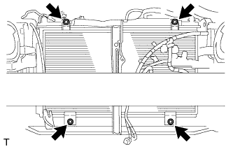
- Torque:
- 5.0 N*m{ 51 kgf*cm , 44 in.*lbf }
| 5. INSTALL RADIATOR OUTLET HOSE |
Install the radiator outlet hose to the radiator assembly and secure it with the clips.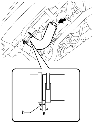
- HINT:
- Make sure that the claws on the clips are facing downward.
- Dimension "a" in the illustration (between the hose end and the clip end) should be less than 1.0 - 5.0 mm.
- Connect the hose until it makes contact with the stopper. (Dimension "b" should be less than 2.5 mm)
- Make sure that the claws on the clips are facing downward.
| 6. INSTALL RADIATOR INLET HOSE |
Install the radiator inlet hose to the radiator assembly and secure it with the clips.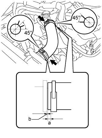
- HINT:
- Make sure that the claws on the clips are positioned as shown in the illustration.
- Dimension "a" in the illustration (between the hose end and the clip end) should be less than 1.0 to 5.0 mm.
- Connect the hose until it makes contact with the stopper. (Dimension "b" should be less than 2.5 mm)
- Make sure that the claws on the clips are positioned as shown in the illustration.
| 7. INSTALL UPPER RADIATOR SUPPORT |
Install the 5 bolts and the upper radiator support.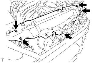
- Torque:
- 8.0 N*m{ 82 kgf*cm , 71 in.*lbf }
Install the 6 wire harness clamps and the No.2 engine room wire.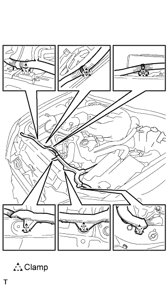
Connect the clamp and the No.2 cooling fan motor connector.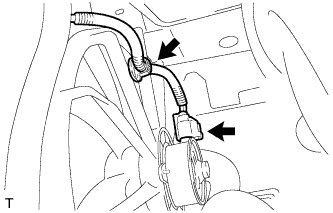
Connect the clamp and the cooling fan motor connector.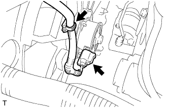
Connect the 4 wire harness clamps and the 3 connectors.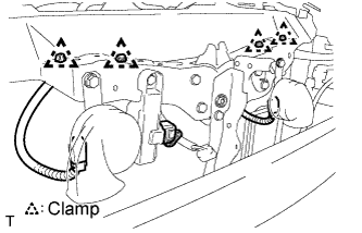
| 8. INSTALL HOOD LOCK ASSEMBLY |
Install the 2 bolts and the hood lock assembly to the upper radiator support.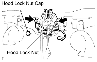
- Torque:
- 8.0 N*m{ 82 kgf*cm , 71 in.*lbf }
Install the hood lock nut and the hood lock nut cap.
- Torque:
- 8.0 N*m{ 82 kgf*cm , 71 in.*lbf }
Connect the connector.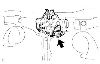
| 9. INSTALL HOOD LOCK CONTROL CABLE COVER |
RHD
Connect the clamp, and install the 3 screws and the hood lock control cable cover.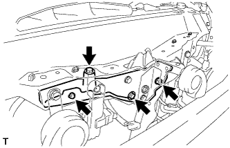
LHD
Connect the clamp, and install the 3 screws and the hood lock control cable cover.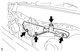
| 10. INSTALL MILLIMETER WAVE RADAR SENSOR ASSEMBLY (w/ Dynamic Radar Cruise Control System) |
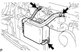 |
Install the millimeter wave radar sensor with the 3 bolts.
- Torque:
- 5.5 N*m{ 56 kgf*cm , 49 in.*lbf }
Connect the connector.
| 11. INSTALL AIR CLEANER CAP WITH AIR CLEANER HOSE |
Install the air cleaner cap with air cleaner hose assembly with the 4 clamps and hose clamp.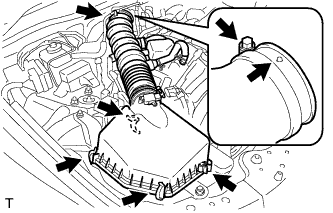
- HINT:
- Be sure to install the air cleaner assembly so that the screw part of the hose clamp is as shown in the illustration.
Install the VSV hose to the air cleaner hose.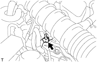
Connect the MAF meter connector and clamp to the air cleaner.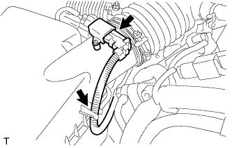
| 12. CONNECT NO. 2 VENTILATION HOSE |
Connect the ventilation hose to the cylinder head cover with the clamp.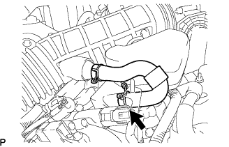
| 13. INSTALL NO. 1 INLET AIR CLEANER |
Install the inlet air cleaner with the bolt.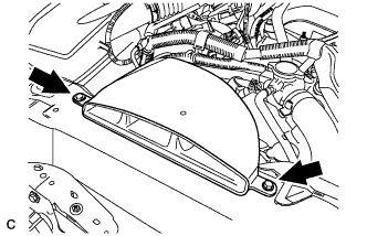
- Torque:
- 5.0 N*m{ 51 kgf*cm , 44 in.*lbf }
| 14. INSTALL RADIATOR SUPPORT OPENING COVER |
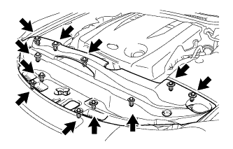
Connect the 2 clips, and install the radiator support opening cover.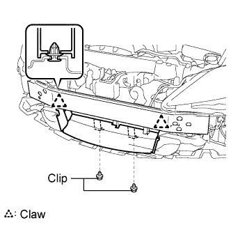
| 15. INSTALL FRONT BUMPER ENERGY ABSORBER |
| 16. INSTALL FRONT BUMPER ASSEMBLY |
| 17. ADD ENGINE COOLANT |
Tighten all the plugs and fill the radiator with TOYOTA Super Long Life Coolant (SLLC).
- Torque:
- 13 N*m{ 130 kgf*cm , 9 ft.*lbf } for cylinder block drain cock plug
Add engine coolant.
- Specified capacity:
- 9.1 liters (9.6 US qts, 8.0 lmp. qts)
- HINT:
- TOYOTA vehicles are filled with TOYOTA SLLC at the factory. In order to avoid damage to the engine cooling system and other technical problems, only use TOYOTA SLLC or similar high quality ethylene glycol based non-silicate, non-amine, non-nitrite, non-borate coolant with long-life hybrid organic acid technology (coolant with long-life hybrid organic acid technology consists of a combination of low phosphates and organic acids).
- TOYOTA vehicles are filled with TOYOTA SLLC at the factory. In order to avoid damage to the engine cooling system and other technical problems, only use TOYOTA SLLC or similar high quality ethylene glycol based non-silicate, non-amine, non-nitrite, non-borate coolant with long-life hybrid organic acid technology (coolant with long-life hybrid organic acid technology consists of a combination of low phosphates and organic acids).
- Contact your TOYOTA dealer for further details.
- Contact your TOYOTA dealer for further details.
Slowly pour coolant into the radiator reservoir until it reaches the FULL line.
Press the inlet and outlet radiator hoses several times by hand, and then check the level of the coolant.
If the coolant level is low, add coolant.
Install the radiator cap and reservoir cap.
Bleed air from the cooling system.
- NOTICE:
- Before starting the engine to warm up the engine, turn the A/C switch OFF.
Warm up the engine until the thermostat opens. While the thermostat is open, circulate the coolant for several minutes.
- HINT:
- The thermostat open timing can be confirmed by pressing the inlet radiator hose by hand, and checking when the engine coolant starts to flow inside the hose.
- NOTICE:
- When pressing the radiator hoses:
- Wear protective gloves.
- Wear protective gloves.
- Be careful as the radiator hoses are hot.
- Be careful as the radiator hoses are hot.
- Keep your hands away from the radiator fans.
- Keep your hands away from the radiator fans.
Maintain the engine speed at 2,000 to 2,500 rpm.
Press the inlet and outlet radiator hoses several times by hand to bleed air.
- NOTICE:
- When pressing the radiator hoses:
- Wear protective gloves.
- Wear protective gloves.
- Be careful as the radiator hoses are hot.
- Be careful as the radiator hoses are hot.
- Keep your hands away from the radiator fans.
- Keep your hands away from the radiator fans.
Stop the engine, and wait until the engine coolant cools down to ambient temperature.
- NOTICE:
- Do not remove the radiator cap while the engine and radiator are still hot. Pressurized, hot engine coolant and steam may be released and cause serious burns.
Check the coolant level in the radiator reservoir.
If the coolant level is low, add SLLC to the radiator reservoir FULL line.
| 18. CHECK FOR ENGINE COOLANT LEAKAGE |
 |
- NOTICE:
- Before performing each inspection, turn the A/C switch OFF.
- CAUTION:
- Do not remove the radiator cap while the engine and radiator are still hot. Pressurized, hot engine coolant and steam may be released and cause serious burns.
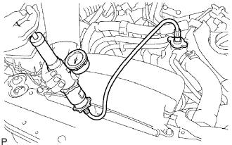
Fill the radiator with coolant and attach a radiator cap tester.
Warm up the engine.
Using a radiator cap tester, increase the pressure inside the radiator to 118 kPa (1.2 kgf*cm2, 17 psi), and check that the pressure does not drop.
If the pressure drops, check the hoses, radiator and water pump for leaks. If no external leaks are found, check the heater core, cylinder block and cylinder head.
| 19. ADJUST MILLIMETER WAVE RADAR SENSOR ASSEMBLY |
 |
- CAUTION:
- Exposure to radio frequency emissions is hazardous to your health. It is hazardous to your health to be within 20 cm (7.9 in.) of the device's radio frequency aperture.
- NOTICE:
- This device complies with FCC radio frequency emission regulations.
- Perform measurements on a level surface.
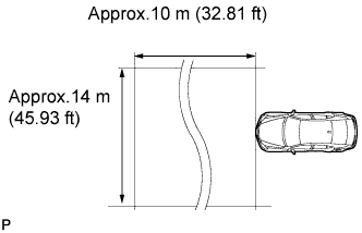
- Make sure that no large pieces of metal are within a 10 m (32.81 ft) x 14 m (45.93 ft) area in front of the vehicle. If possible, the surrounding area should also be free of large metal objects.
- This device complies with FCC radio frequency emission regulations.
Before adjusting the radar beam axis, prepare the vehicle as follows:
Check the tire pressure and adjust it if necessary.
Remove all excess weight from the vehicle (luggage, heavy objects, etc. ).
Check and adjust the vertical direction of the radar sensor.
Remove dust, oil, and foreign matter from the radar sensor's level rack.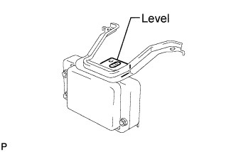
Set a level on the radar sensor's level rack.
Check that the air bubble is within the red frame on the level.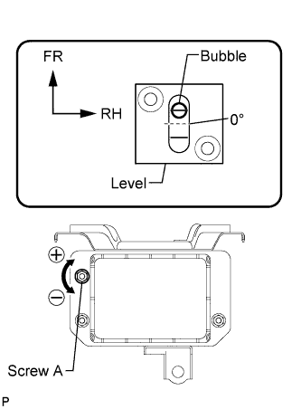
- OK:
- The air bubble is within the red frame on the level.
If the bubble is not within the red frame, use a hexagon wrench to adjust screw A until the air bubble is within the red frame.
- HINT:
- The adjustable range within the red frame on the level is + - 0.2°.
- The target angle is +0.2° (upward angle of 0.2°).
- The adjustable range within the red frame on the level is + - 0.2°.
- Result:
Adjustment Direction
Adjustment Procedure
Adjustment Angle
Vertical adjustment
- Upward direction: Turn screw A to negative (-) side
- Downward direction: Turn screw A to positive (+) side
Approx. 1.0° per turn
- Upward direction: Turn screw A to negative (-) side
Adjust the reflector height.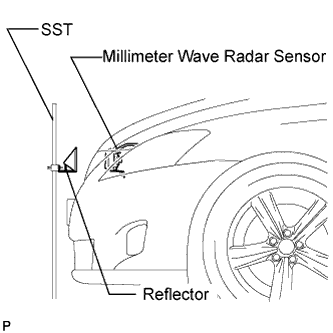
Adjust the reflector so that the center of the SST reflector is the same height as the millimeter wave radar sensor.
- SST
- 09870-60000
(09870-60010, 09870-60040)
- HINT:
- Prepare a 10 m (32.81 ft) string, a string with a sharp-pointed weight (plumb bob), and a 5 m (16.41 ft) tape measure.
Place the reflector.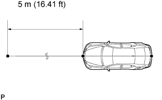
Hang the string (with weight) from the center of the vehicle's rear emblem. Mark the vehicle's rear center point on the ground. Repeat the same procedure for the front of the vehicle.
Set one end of the 10 m (32.82 ft) string on the vehicle's rear center point. Run the string over the vehicle's front center point to a position 5 m (16.41 ft) beyond the vehicle front center point, as shown in the illustration. Mark the 5 m (16.41 ft) position.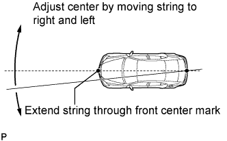
Using a tape measure, measure 12 mm (0.47 in.) to the left of the 5 m (16.41 ft) position. Place the reflector at that position.
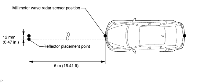
- NOTICE:
- Perform the operation as precisely as possible.
Adjust the radar beam axis.
Connect the intelligent tester to the DLC3.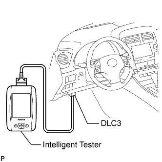
Turn the engine switch on (IG).
Turn the intelligent tester main switch on, and turn the cruise control main switch on.
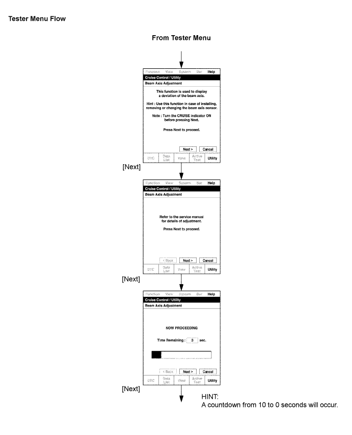
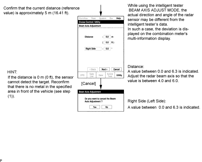
Check and adjust the horizontal direction of the radar sensor.
Check that the divergence of the radar beam axis is 0° .
- Standard:
- 0° (Both right and left)
- If the axis is not as specified, use a hexagon wrench to adjust screw B until the divergence of the radar beam axis is 0°.
Based on the measured divergence of the beam axis, turn and adjust screw B for horizontal adjustment of the millimeter wave radar sensor using a hexagon wrench.
- Result:
Adjustment Direction
Adjustment Procedure
Adjustment Angle
Horizontal adjustment
- Right direction: Turn screw B to positive (+) side.
- Left direction: Turn screw B to negative (-) side.
Approx. 0.33° per turn
- Right direction: Turn screw B to positive (+) side.
- HINT:
- If "LEFT SIDE: 1.0°" is displayed, the divergence is 1.0° in the left direction. Turn screw B approximately 3 turns to the negative (-) side.
- If the value does not change to 0°, it is possible that the sensor is aiming at something different. Reconfirm that there are no reflective materials in the surrounding area.
- If "LEFT SIDE: 1.0°" is displayed, the divergence is 1.0° in the left direction. Turn screw B approximately 3 turns to the negative (-) side.
Reset the radar sensor's driving learning values. Prepare a type of metal that can block radio waves, such as aluminum foil. Cover the radar sensor's left half with the aluminum foil for 10 seconds.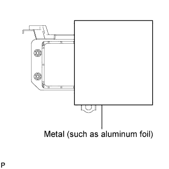
- NOTICE:
- Be sure to keep the reflector in place and make sure that there is nothing between the sensor's left half and the reflector.
- HINT:
- When the reset is completed, the buzzer sounds for 10 seconds.
Disconnect the intelligent tester from the DLC3.
Recheck and readjust the vertical direction of the radar sensor.
Set a level on the radar sensor's level rack.
Check that the air bubble is within the red frame on the level.
- OK:
- The air bubble is within the red frame on the level.
- If the bubble is not within the red frame, use a hexagon wrench to adjust screw A until the air bubble is within the red frame.
- HINT:
- The adjustable range within the red frame on the level is + -0.2°.
- The target angle is +0.2° (upward angle of 0.2°).
- The adjustable range within the red frame on the level is + -0.2°.
- Result:
Adjustment Direction
Adjustment Procedure
Adjustment Angle
Vertical adjustment
- Upward direction: Turn screw A to negative (-) side
- Downward direction: Turn screw A to positive (+) side
Approx. 1.0°per turn
- Upward direction: Turn screw A to negative (-) side
| 20. PUT VEHICLE UNDER THESE CONDITIONS |
Adjust the tire pressure to the correct value range.
Start the engine and charge the battery.
| 21. FOG LIGHT AIMING ADJUSTMENT |
Adjust the fog light aim into the specified range by turning aiming screw with a screwdriver.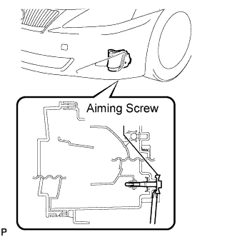
- NOTICE:
- The final turn of the aiming screw should be made in the clockwise direction. If the screw is tightened excessively, loosen it and then retighten it, so that the final turn of the screw is in the clockwise direction.
| 22. FOG LIGHT AIMING INSPECTION |
Cover or disconnect the connector of the fog light on the opposite side to prevent light from the fog light not being inspected from affecting fog light aiming inspection.
Start the engine.
Turn on the fog light and make sure that the cutoff line falls within the specified area, as shown in the illustration.
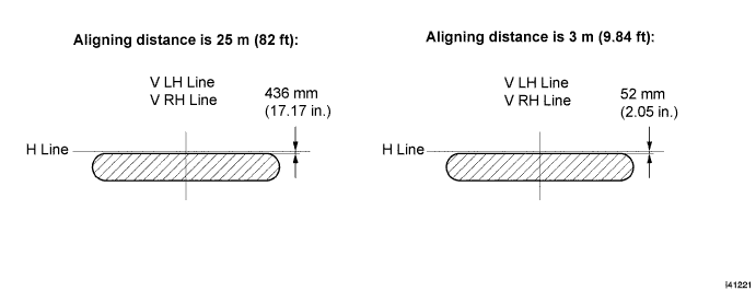
| 23. INSTALL ENGINE UNDER COVER |
| 24. INSTALL V-BANK COVER SUB-ASSEMBLY |
Engage the 2 clips on the front of the cover, and then engage the clip on the rear to install the V-bank cover.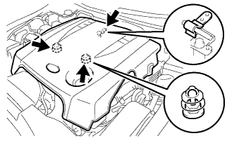
- NOTICE:
- Be sure to engage the clips securely.
- Do not apply excessive force or do not hit the cover to engage the clips. This may cause the cover to break.
- Be sure to engage the clips securely.
| 25. INSTALL ENGINE ROOM SIDE COVER LH |
Install the side cover with the 5 clips.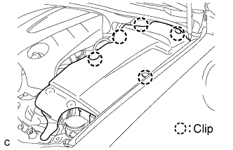
| 26. INSTALL ENGINE ROOM SIDE COVER RH |
Install the side cover with the 2 clips.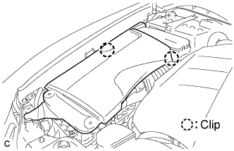
| 27. INSTALL COOL AIR INTAKE DUCT SEAL |
Install the intake duct seal with the 11 clips.