INSTALLATION
Removal / installation
| 1. INSTALL NEUTRAL START SWITCH ASSEMBLY |

Install the park/neutral position switch to the manual valve shaft.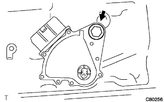

Temporarily install the bolt.
Install a new lock washer and the nut.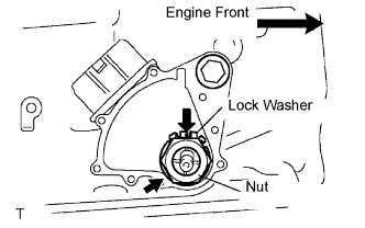
- Torque:
- 6.9 N*m{ 70 kgf*cm , 61 in.*lbf }
Temporarily install the control shaft lever.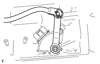
Turn the control shaft lever counterclockwise until it stops, and turn it clockwise 2 notches to set it to the N position.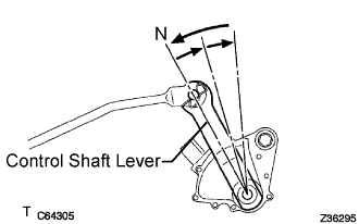
Remove the transmission control shaft lever.
Align the neutral alignment mark line with the switch groove, and tighten the adjusting bolt.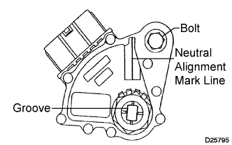
- Torque:
- 13 N*m{ 130 kgf*cm , 9 ft.*lbf }
Using a screwdriver, bend the tabs of the lock washer.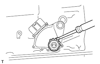
Install the transmission control shaft lever RH with the nut.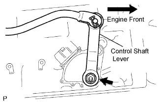
- Torque:
- 16 N*m{ 163 kgf*cm , 12 ft.*lbf }
Connect the park/neutral position switch connector.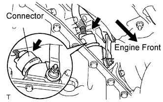
| 2. INSTALL FLOOR SHIFT GEAR SHIFTING ROD SUB-ASSEMBLY |
Temporarily tighten the floor shift gear shifting rod sub-assembly with the nut.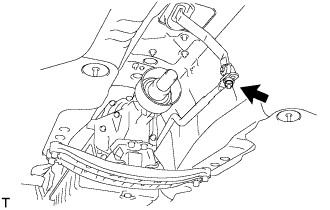
| 3. ADJUST SHIFT LEVER POSITION |
Remove the nut and disconnect the shifting rod.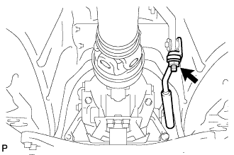
Turn the control shaft lever of the park/neutral position switch counterclockwise until it stops, and turn it clockwise 2 notches to set it to the N position.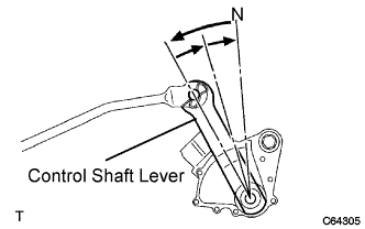
Move the shift lever to the N position and tighten the nut while lightly pushing the lever toward the R position.
- NOTICE:
- Do not push the shift lever too hard.
After adjustment, check that the shift lever moves smoothly and the shift lever and gear operate correctly.
| 4. INSPECT SHIFT LEVER POSITION |
When shifting from the P to R position with the engine switch on (IG) and the brake pedal depressed, make sure that the shift lever moves smoothly and moves correctly into the position.
Start the engine and make sure that the vehicle moves forward when shifting from the N to D position and moves rearward when shifting to the R position.
If operation cannot be done as specified, inspect the park/neutral position switch assembly and check the shift lever assembly installation condition.
| 5. INSPECT PARK/NEUTRAL POSITION SWITCH ASSEMBLY |
Measure the resistance according to the value(s) in the table below.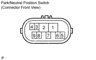
- Standard resistance:
Shift Position
Tester Connection
Specified Condition
P
2 - 6 and 4 - 5
Below 1 Ω
Except P
2 - 6 and 4 - 5
10 kΩ higher
R
1 - 2
Below 1 Ω
Except R
1 - 2
10 kΩ higher
N
2 - 9 and 4 - 5
Below 1 Ω
Except N
2 - 9 and 4 - 5
10 kΩ higher
D, S, "+" and "-"
2 - 7
Below 1 Ω
Except D, S, "+" and "-"
2 - 7
10 kΩ higher
| 6. INSTALL NO. 2 ENGINE UNDER COVER |