INSTALLATION
Removal / installation
| 1. INSTALL TORQUE CONVERTER CLUTCH ASSEMBLY |

Using calipers and a straight edge, measure dimension A between the engine and the end surface of the drive plate (#1).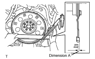

Aligning the matchmarks on the transmission case and torque converter, engage the splines of the input shaft and turbine runner.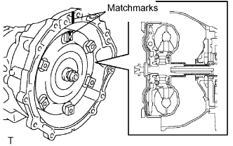
Engage the splines of the stator shaft and stator while turning the torque converter clutch.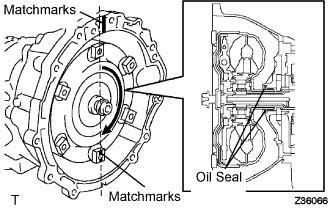
- HINT:
- Turn the torque converter clutch approximately 180°.
Turn the torque converter clutch and align the matchmarks on the torque converter clutch and transmission case to engage the key of the oil pump drive gear into the slot on the torque converter clutch.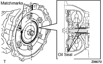
- NOTICE:
- Do not push on the torque converter when aligning the matchmarks.
Using calipers and a straight edge, measure dimension B shown in the illustration and check that B is greater than A measured in step (#1).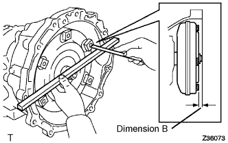
- Standard:
- A + 1 mm (0.04 in.) or more
| 2. INSTALL TRANSMISSION OIL COOLER |
Coat 2 new O-rings with ATF and install them to the transmission oil cooler.
Install the transmission oil cooler to the automatic transmission assembly with the 3 bolts.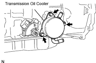
- Torque:
- 21 N*m{ 214 kgf*cm , 15 ft.*lbf }
| 3. INSTALL TRANSMISSION CONTROL SHAFT LEVER RH |
Install the transmission control shaft to the neutral start switch assembly with the nut.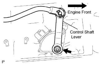
- Torque:
- 16 N*m{ 163 kgf*cm , 12 ft.*lbf }
| 4. INSTALL REAR NO. 1 ENGINE MOUNTING INSULATOR |
Install the rear No. 1 engine mounting insulator to the automatic transmission assembly with the 4 bolts.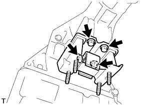
- Torque:
- 12 N*m{ 120 kgf*cm , 9 ft.*lbf }
| 5. INSTALL AUTOMATIC TRANSMISSION ASSEMBLY |
Install the automatic transmission assembly to the engine with the 9 bolts.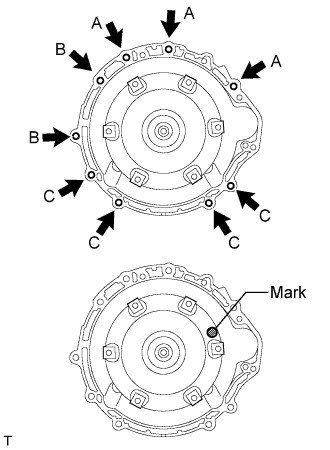
- Torque:
- Bolts A and B:
- 71 N*m{ 724 kgf*cm , 52 ft.*lbf }
- Bolt C:
- 37 N*m{ 377 kgf*cm , 27 ft.*lbf }
- HINT:
- Make sure that the mark is as shown in the illustration.
- Do not use excess force to pry on the transmission assembly.
- Make sure that the mark is as shown in the illustration.
| 6. INSTALL WATER BY-PASS HOSE |
Tilt down the automatic transmission assembly.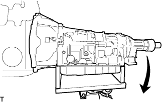
Install the 2 water by-pass hoses to the transmission assembly.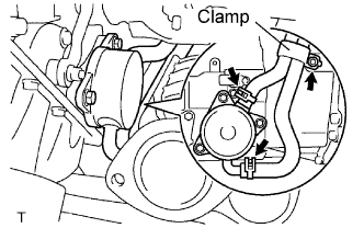
Install the water by-pass hose clamp with the bolt.
- Torque:
- 20 N*m{ 204 kgf*cm , 15 ft.*lbf }
| 7. INSTALL WIRE HARNESS |
Install the wire harness clamps to the automatic transmission assembly with the 2 bolts.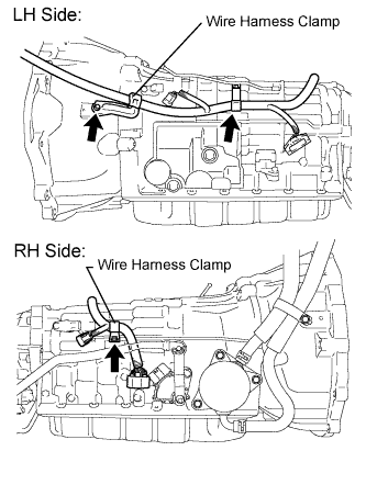
- Torque:
- 10 N*m{ 102 kgf*cm , 7 ft.*lbf }
| 8. INSTALL CONNECTOR |
Connect the park/neutral position switch connector, transmission wire connector, and 2 transmission revolution sensor connectors.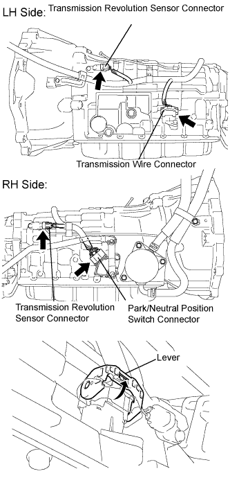
- HINT:
- Push up the lever until the claw of the transmission wire connector makes a connection sound.
| 9. INSTALL ENGINE REAR MOUNTING MEMBER |
Tilt up the automatic transmission assembly.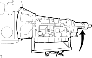
Install the engine rear mounting member to the automatic transmission assembly with the 4 nuts.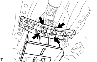
- Torque:
- 13 N*m{ 133 kgf*cm , 10 ft.*lbf }
Install the engine rear mounting member to the body with the 4 bolts.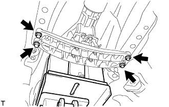
- Torque:
- 26 N*m{ 260 kgf*cm , 19 ft.*lbf }
| 10. INSTALL FLOOR SHIFT GEAR SHIFTING ROD SUB-ASSEMBLY |
Temporarily tighten the floor shift gear shifting rod sub-assembly with the nut.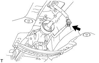
| 11. INSTALL NO. 1 EXHAUST PIPE SUPPORT BRACKET SUB-ASSEMBLY |
Install the No. 1 exhaust pipe support bracket sub-assembly to the automatic transmission assembly with the 2 bolts.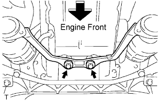
- Torque:
- 43 N*m{ 438 kgf*cm , 32 ft.*lbf }
| 12. INSTALL DRIVE PLATE & TORQUE CONVERTER CLUTCH SETTING BOLT |
Install the 6 torque converter clutch setting bolts.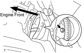
- Torque:
- 41 N*m{ 418 kgf*cm , 30 ft.*lbf }
- HINT:
- First install the black colored bolt and then the remaining 5 bolts.
| 13. INSTALL STARTER ASSEMBLY |
Install the starter with the 2 bolts.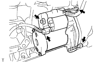
- Torque:
- 58 N*m{ 591 kgf*cm , 43 ft.*lbf }
Connect the wire harness to terminal 30 and install the nut, and then attach the terminal cap.
- Torque:
- 9.8 N*m{ 100 kgf*cm , 87 in.*lbf }
Connect the terminal 50 connector to the starter assembly.
| 14. INSTALL EXHAUST MANIFOLD SUB-ASSEMBLY LH |
Install a new gasket and the exhaust manifold with 6 new nuts.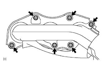
- Torque:
- 21 N*m{ 214 kgf*cm , 15 ft.*lbf }
Connect the air fuel ratio sensor (for sensor 1) connector.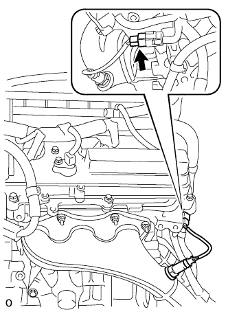
Install the engine wire bracket with the bolt (A).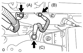
- Torque:
- 10 N*m{ 102 kgf*cm , 7 ft.*lbf }
Install the ground cable with the 2 bolts (B, C).
- Torque:
- Bolt (B):
- 10 N*m{ 102 kgf*cm , 7 ft.*lbf }
- Bolt (C):
- 13 N*m{ 133 kgf*cm , 10 ft.*lbf }
| 15. INSTALL PROPELLER SHAFT WITH CENTER BEARING ASSEMBLY |
Remove the SST from the transmission.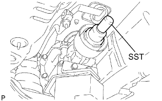
- SST
- 09325-40010
Insert the yoke of the intermediate shaft into the transmission.
- HINT:
- Be careful not to damage the oil seal.
Install the 2 center support bearing washers and center support bearing. (for automatic transmission)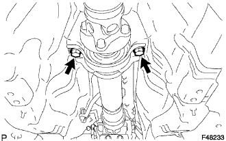
Install the 2 center support bearing washers, center support bearing and 2 center support bearing dampers. (for manual transmission)
Temporarily tighten the 2 bolts.
Align the matchmarks on the propeller shaft flange and differential companion flange, and connect the shaft with the 4 bolts, washers and nuts.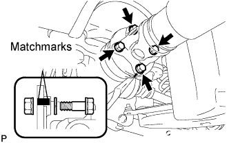
- Torque:
- 74 N*m{ 750 kgf*cm , 54 ft.*lbf }
Adjust the dimension between the edge surface of the center support bearing and the edge surface of the cushion to 11.5 to 13.5 mm (0.4528 to 0.5315 in.) as shown in illustration.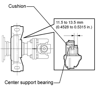
Check that the center line of the bracket is perpendicular to the shaft axial direction.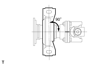
Tighten the 2 bolts.
- Torque:
- 49 N*m{ 500 kgf*cm , 36 ft.*lbf }
| 16. INSTALL OUTSIDE AIR GUIDE PLATE RH |
Install the air guide plate outside RH with the 4 nuts.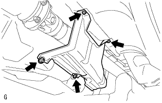
- Torque:
- 5.4 N*m{ 55 kgf*cm , 48 in.*lbf }
| 17. CONNECT CABLE TO NEGATIVE BATTERY TERMINAL |
| 18. ADJUST SHIFT LEVER POSITION |
Remove the nut and disconnect the shifting rod.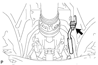
Turn the control shaft lever of the park/neutral position switch counterclockwise until it stops, and turn it clockwise 2 notches to set it to the N position.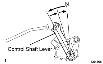
Move the shift lever to the N position and tighten the nut while lightly pushing the lever toward the R position.
- NOTICE:
- Do not push the shift lever too hard.
After adjustment, check that the shift lever moves smoothly and the shift lever and gear operate correctly.
| 19. INSPECT SHIFT LEVER POSITION |
When shifting from the P to R position with the engine switch on (IG) and the brake pedal depressed, make sure that the shift lever moves smoothly and moves correctly into the position.
Start the engine and make sure that the vehicle moves forward when shifting from the N to D position and moves rearward when shifting to the R position.
If operation cannot be done as specified, inspect the park/neutral position switch assembly and check the shift lever assembly installation condition.
| 20. INSTALL FRONT FLOOR NO. 1 HEAT INSULATOR |
Install the No. 1 heat insulator with the 4 nuts.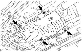
- Torque:
- 5.4 N*m{ 55 kgf*cm , 48 in.*lbf }
| 21. INSTALL FRONT EXHAUST PIPE ASSEMBLY |
Using a vernier caliper, measure the free length of the compression springs.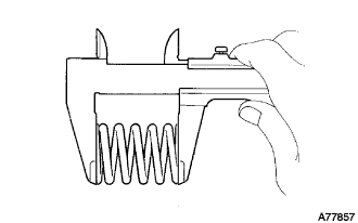
- Minimum length:
- 38.5 mm (1.516 in.)
Install a new gasket to the rear end of the front exhaust pipe.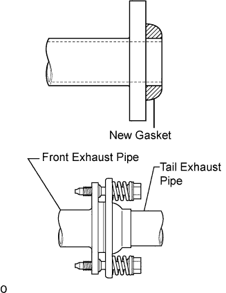
- NOTICE:
- Be careful with the installation direction of the gasket.
- Be careful with the installation direction of the gasket.
- Do not reuse the gasket.
- Do not reuse the gasket.
- To ensure a proper seal, do not use the tail exhaust pipe to force the gasket onto the front exhaust pipe.
- HINT:
- Using a plastic hammer, uniformly strike the gasket so that the gasket and front exhaust pipe are properly fit.
- To ensure a proper seal, do not use the tail exhaust pipe to force the gasket onto the front exhaust pipe.
Install 3 new gaskets and front exhaust pipe assembly.
- CAUTION:
- Do not reuse the gaskets.
Install the 2 bolts and 2 compression springs.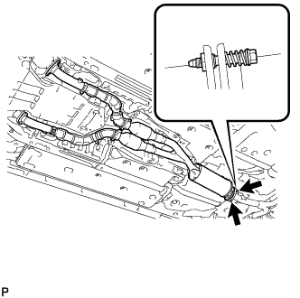
- Torque:
- 43 N*m{ 438 kgf*cm , 32 ft.*lbf }
Install 4 new nuts and 4 bolts.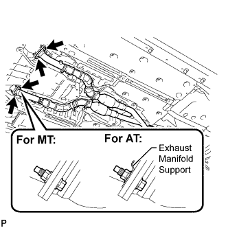
- Torque:
- 62 N*m{ 632 kgf*cm , 46 ft.*lbf }
- NOTICE:
- Do not reuse the nuts.
| 22. INSTALL OXYGEN SENSOR |
Before installing the heated oxygen sensors, twist the sensor wires counterclockwise 4 turns.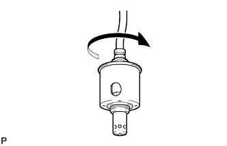
Using the SST, install the heated oxygen sensors to the front exhaust pipe.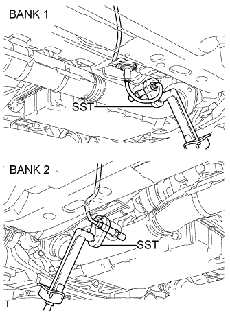
- SST
- 09224-00010
- Torque:
- 44 N*m{ 449 kgf*cm , 33 ft.*lbf }
After installing the sensors, check that the sensor wires are not twisted.
If the sensor wires are twisted, reinstall them.
Install the grommets of the heated oxygen sensors.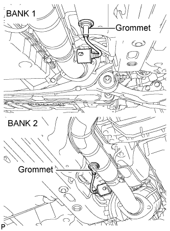
| 23. INSTALL FRONT CENTER FLOOR BRACE |
Install the front center floor brace with the 4 bolts.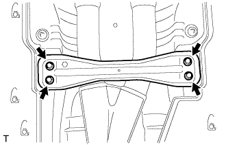
- Torque:
- 7.4 N*m{ 75 kgf*cm , 65 in.*lbf }
| 24. INSTALL REAR NO. 1 FLOOR PANEL BRACE |
Install the rear No. 1 floor panel brace with the 4 bolts.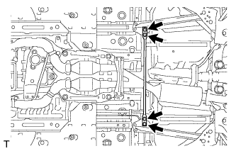
- Torque:
- 19 N*m{ 194 kgf*cm , 14 ft.*lbf }
| 25. ADD COOLANT |
| 26. ADD AUTOMATIC TRANSMISSION FLUID |
| 27. ADJUST COOLANT |
| 28. CHECK FOR ENGINE COOLANT LEAKS |
 |
- NOTICE:
- Before performing each inspection, turn the A/C switch OFF.
- CAUTION:
- Do not remove the radiator cap while the engine and radiator are still hot. Pressurized, hot engine coolant and steam may be released and cause serious burns.
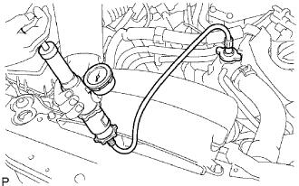
Fill the radiator with coolant and attach a radiator cap tester.
Warm up the engine.
Using a radiator cap tester, increase the pressure inside the radiator to 118 kPa (1.2 kgf*cm2, 17 psi), and check that the pressure does not drop.
If the pressure drops, check the hoses, radiator and water pump for leaks. If no external leaks are found, check the heater core, cylinder block and cylinder head.
| 29. CHECK FOR EXHAUST GAS LEAKS |
| 30. REMOVE ENGINE UNDER COVER AIR GUIDE BRACKET |
Install the engine under cover air guide bracket with the 2 bolts.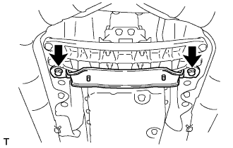
- Torque:
- 26 N*m{ 265 kgf*cm , 19 ft.*lbf }
| 31. INSTALL NO. 2 ENGINE UNDER COVER |
| 32. INSTALL ENGINE UNDER COVER |
| 33. INSTALL ENGINE ROOM SIDE COVER LH |
Install the side cover with the 5 clips.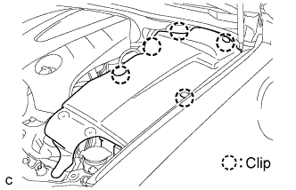
| 34. INSTALL COOL AIR INTAKE DUCT SEAL |
Install the intake duct seal with the 11 clips.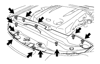
| 35. RESET MEMORY |
| 36. PERFORM INITIALIZATION |
(Click here).