INSTALLATION
Removal / installation
| 1. INSTALL AUTOMATIC TRANSMISSION EXTENSION HOUSING OIL SEAL |

Coat the lip of a new oil seal with MP grease.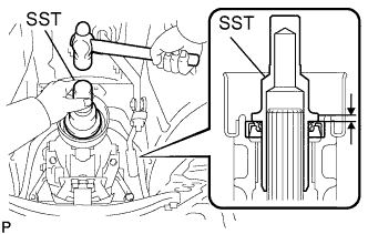

Using SST and a hammer, drive in a new oil seal.
- SST
- 09325-40010
- Oil seal drive in depth:
- 5.4 to 5.8 mm (0.213 to 0.228 in.)
- NOTICE:
- Keep the lip free from foreign matter.
- Do not tap the oil seal at an angle.
- Keep the lip free from foreign matter.
| 2. INSTALL PROPELLER SHAFT WITH CENTER BEARING ASSEMBLY |
Remove the SST from the transmission.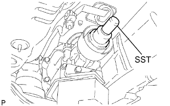
- SST
- 09325-40010
Insert the yoke of the intermediate shaft into the transmission.
- HINT:
- Be careful not to damage the oil seal.
Install the 2 center support bearing washers and center support bearing. (for automatic transmission)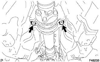
Install the 2 center support bearing washers, center support bearing and 2 center support bearing dampers. (for manual transmission)
Temporarily tighten the 2 bolts.
Align the matchmarks on the propeller shaft flange and differential companion flange, and connect the shaft with the 4 bolts, washers and nuts.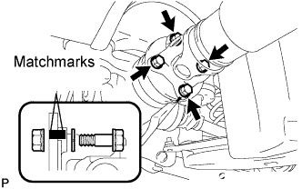
- Torque:
- 74 N*m{ 750 kgf*cm , 54 ft.*lbf }
Adjust the dimension between the edge surface of the center support bearing and the edge surface of the cushion to 11.5 to 13.5 mm (0.4528 to 0.5315 in.) as shown in illustration.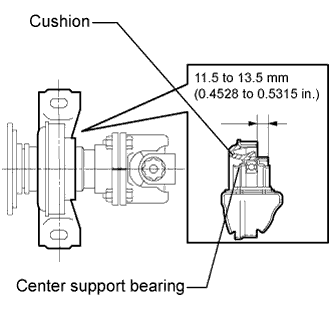
Check that the center line of the bracket is perpendicular to the shaft axial direction.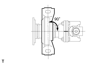
Tighten the 2 bolts.
- Torque:
- 49 N*m{ 500 kgf*cm , 36 ft.*lbf }
| 3. REMOVE OUTSIDE AIR GUIDE PLATE RH |
Install the air guide plate outside RH with the 4 nuts.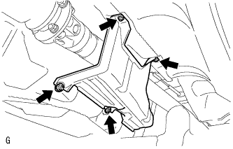
- Torque:
- 5.4 N*m{ 55 kgf*cm , 48 in.*lbf }
| 4. INSTALL FRONT FLOOR NO. 1 HEAT INSULATOR |
Install the No. 1 heat insulator with the 4 nuts.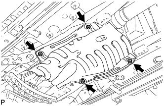
- Torque:
- 5.4 N*m{ 55 kgf*cm , 48 in.*lbf }
| 5. INSTALL FRONT EXHAUST PIPE ASSEMBLY |
Using a vernier caliper, measure the free length of the compression springs.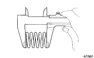
- Minimum length:
- 38.5 mm (1.516 in.)
Install a new gasket to the rear end of the front exhaust pipe.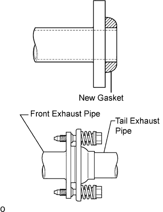
- NOTICE:
- Be careful with the installation direction of the gasket.
- Be careful with the installation direction of the gasket.
- Do not reuse the gasket.
- Do not reuse the gasket.
- To ensure a proper seal, do not use the tail exhaust pipe to force the gasket onto the front exhaust pipe.
- HINT:
- Using a plastic hammer, uniformly strike the gasket so that the gasket and front exhaust pipe are properly fit.
- To ensure a proper seal, do not use the tail exhaust pipe to force the gasket onto the front exhaust pipe.
Install 3 new gaskets and front exhaust pipe assembly.
- CAUTION:
- Do not reuse the gaskets.
Install the 2 bolts and 2 compression springs.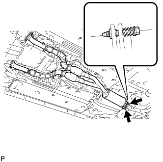
- Torque:
- 43 N*m{ 438 kgf*cm , 32 ft.*lbf }
Install 4 new nuts and 4 bolts.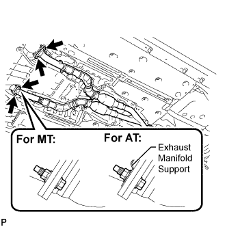
- Torque:
- 62 N*m{ 632 kgf*cm , 46 ft.*lbf }
- NOTICE:
- Do not reuse the nuts.
| 6. INSTALL OXYGEN SENSOR |
Before installing the heated oxygen sensors, twist the sensor wires counterclockwise 4 turns.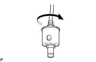
Using the SST, install the heated oxygen sensors to the front exhaust pipe.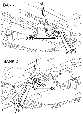
- SST
- 09224-00010
- Torque:
- 44 N*m{ 449 kgf*cm , 33 ft.*lbf }
After installing the sensors, check that the sensor wires are not twisted.
If the sensor wires are twisted, reinstall them.
Install the grommets of the heated oxygen sensors.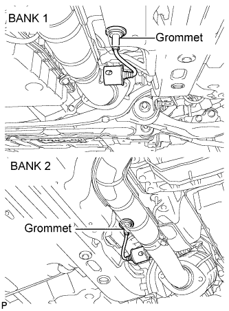
| 7. INSTALL FRONT CENTER FLOOR BRACE |
Install the front center floor brace with the 4 bolts.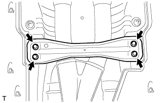
- Torque:
- 7.4 N*m{ 75 kgf*cm , 65 in.*lbf }
| 8. INSTALL REAR NO. 1 FLOOR PANEL BRACE |
Install the rear No. 1 floor panel brace with the 4 bolts.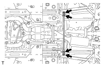
- Torque:
- 19 N*m{ 194 kgf*cm , 14 ft.*lbf }
| 9. ADD AUTOMATIC TRANSMISSION FLUID |
| 10. CHECK FOR EXHAUST GAS LEAKS |
| 11. INSTALL NO. 2 ENGINE UNDER COVER |